890
Model Code Page
51. Brake system
1. 8. 1998
6000--8750 511 6
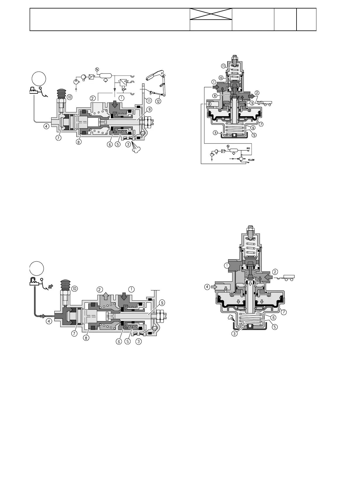
E. Control v alve for trailer brakes
A
Function,fig.A(not braking):
In the neutral position spring 5 presses sleeve 6 against the
valve body , passage from inlet port 1 forwards is closed.
Passage 2 to the trailer coupling (and to the one---line system
contr ol valve) is connected to outlet port 3.
Adjusting hand brake
Hand brake adjustment is made with the aid of rod 12.
Adjustment: Adjust the rod (12) length so thatthe trailer brake
coupling (yellow)gives checkpressureof 6,2 --- 7,5 bar when
the hand brake lever is in the secondnotch of the ratchetplate.
B
Function,fig.B(when braking):
Brake pedal hydraulic pressure via po rt 4 and piston 7 pus-
hes it and the adjusting piston 8 to the right.
Connection from port 2 to outlet hole is closed, and passage
from port 1 to 2 is opened. Compressed---air is directed via
port 2 thetrailerbrakevalve.
Pressure which acts against adjusting piston 8 pushes the
piston (+piston 7) against the brake hydraulic pressure to the
left and connec t ion between ports 1--- > 2 is closed.
Balance situation is achieved.
F. Control valve of one ---line system
A
Fig. A (not braking)
Spring 5 holds membrane+sleeve 6 up. Upper end of valve
spindle 8 has opened passagefrom inletport 1 to trailer brake
port 2. Pressure air flows from tractor reservoir via ports 1 and
2tothetrailerbrakes.
Simultaneously in port 2 pressure acts on the underside of
piston 1.
C
Function,fig.C(when braking):
When depressing the brake pedal pilot pressure from the trai-
ler control valve port 4. Pressure affect the upper part of
memphrane 7, and moves the memphrane and sleeve 6
downwards against spring 5. P assage from port 2 to sleeve
6 internal hole opens.
Pressure flows from port 2 via sleeve 6 and cover hole 3 to
outdoors to give quick pressure drop for trailer pre---braking.
The pressure drop causes an action of trailer brake valve in
one---line system.
NOTE! During braking replacing air does not flow into the trai-
ler brake system.
--- The one---line system working pressure (5,2 bar) is lower
than that in the two---line system. Control valve lowers the sys-
tem pressure from 7 bar to 5 bar. Contrary to the two---line sys-
tem coupling(yellow), the black coupling of the one---line sys-
tem is under pr essure when no t braking.
The control valve does not require maintenance.