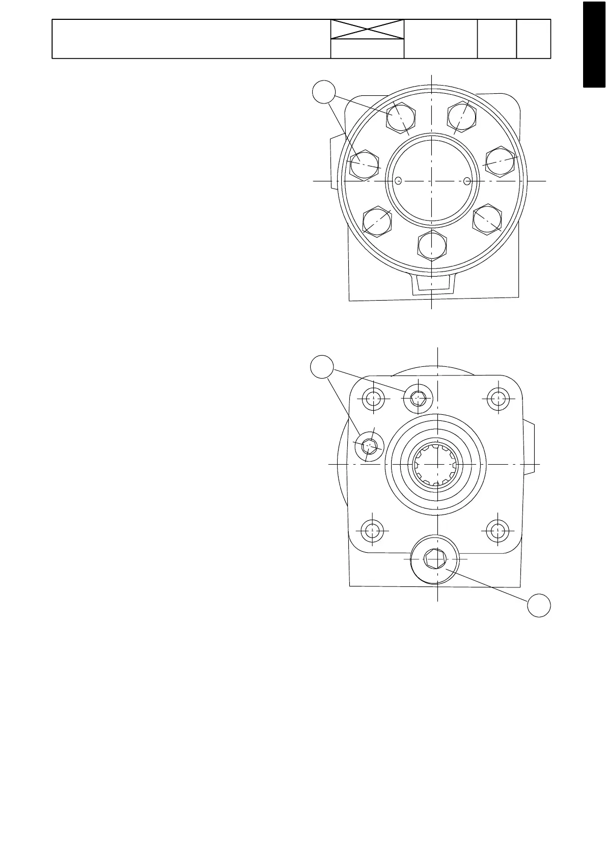
Figure 5. Steering valve lower face
A. Anti ---cavitation valves
Figure 6. Steering valve upper face
B. Shock valves
C. Pressure---limiting valve
935
Model Code Page
61. Steering system
8. 11. 1990
6000--8750 610 7
Steering valve, description
Seefigure4onpreviouspage.
The steering valve consists of a metering unit (rotor set) and
a valve unit. The rotor set consists of a rotor ring (4) with seven
internal teeth and a rot or ( 5) with six external teeth. The valve
unit consists of a valve housing (6), outer valve slide (8) and
inner valve slide (7).
The inner slide (7) is directly actuated by the steering wheel.
The outer valve slide (8) is mechanically connected to the
rotor (5) by a cross pin and rotor shaft (9). The cross pin which
runs through both valve slides permits the inner valve slide to
move 8˚ in both directions independent of the outer valve
slide.
When the steering wheel is in the rest position, centring
springs keep the inner and the outer valve slides in neutral (in
relation to each other) and the oil flows freely through the
steering valve. The passages to the steering cylinder are kept
closed and the steering cylinder cannot move.
When the steering wheel is turned, the inner valve slide is
turned in relation to the outer valve slide. The neutral---position
passages become restricted at the same time the passages
down to the measuring unit and on to the steering cylinder
gradually open. Simultaneously the return oil from the other
side of the steering cylinder flows back via the steering valve.
The oil flow from the pump through the valve makes the rotor
and the outer valve slide turn in the same direction as the
steering wheel and the inner valve slide.
When the steering wheel is not turned any further and kept
still, the centring springs bring the outer and the inner valve
slide back into the neutral position The passages to the steer-
ing cylinder clo se and the oil flows freely again through the
steering valve.
When the hydraulic pump does not supply any oil, the meter-
ing unit of the steering valve acts as a manually powered
pump. The oil which is drawn from the steering cylinder and
thereturnlineviathenon---returnvalve(3)isdeliveredtothe
other side of the steering cylinder when the steering wheel
(and inner valve slide 7) is turned 8˚.Thecrosspinthenalso
makes the following parts turn: the outer valve s lide (8), rotor
shaft (9) and rotor (5). Shocks and knocks against the steering
wheel are dampened by the two shock valves (1) which are
fitted in the steering valve.
The shock valves are combined with anti---cavitatio n valves
(point A in figure 5) in order to keep the cylinder fully supplied
with oil at all times.
A
B
C