29. See Figure 154. Install steel core gasket, if used, or
apply a bead of Silicone Sealant (see SECTION 9 -
SPECIFICATIONS - Lubricants and Sealants) 0.06-0.10
inches (1.5-2.5 mm) thick to crankcase cover. Bead
must be a continuous closed loopwith no gapsand an
overlapnot exceeding 0.20 inches (5 mm) in thetwo
areas shown.
154
NOTE: Crankcase cover must be installed within five minutes
of application. If time limit is exceeded, scrape off silicone
sealant and reapply.
30. Install oil seal protector sleeve on crankshaft.
NOTE: Use black electrical tape if oil seal protector sleeve is
not available.
31. Install crankcase cover onto 2 locating pins.
32. Remove oil seal protector sleeve (or black electrical tape)
from crankshaft.
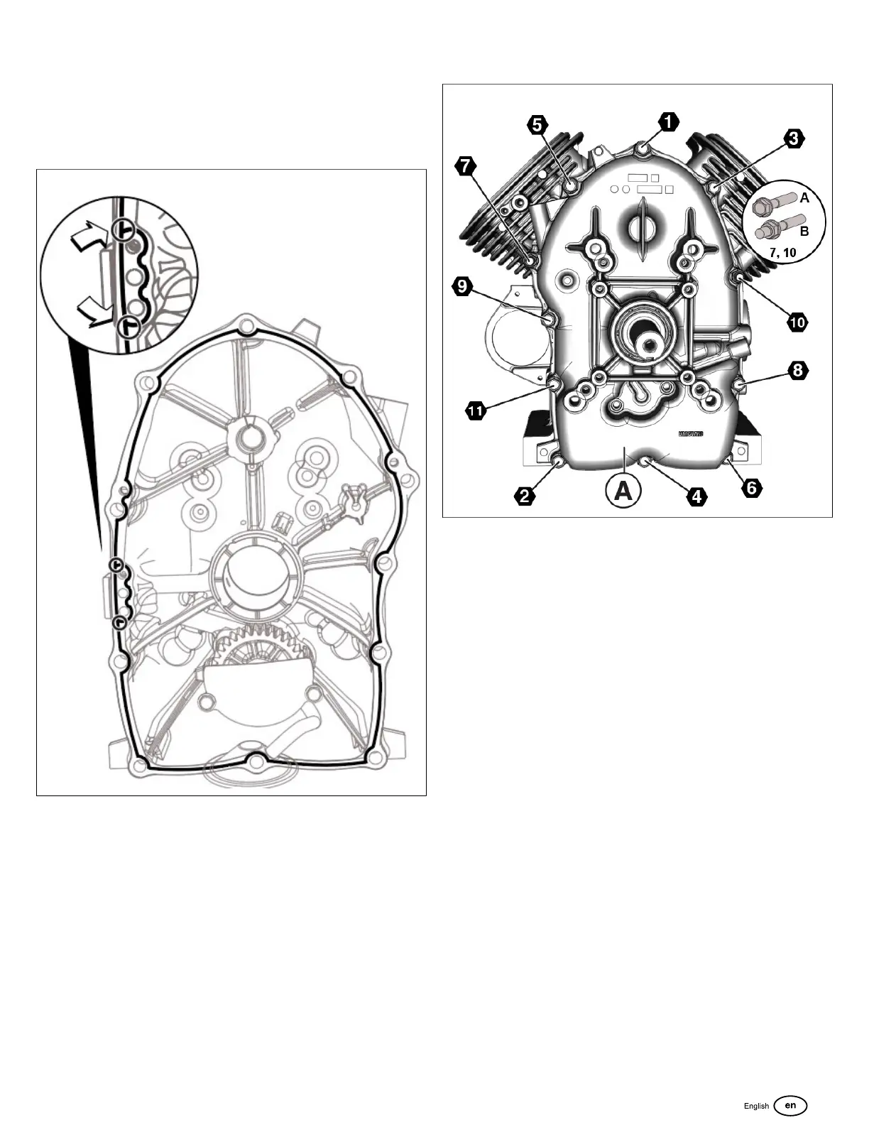
33. Start 11 fasteners to secure crankcase cover (A, Figure
155) to crankcase. Proceed as follows:
155
NOTE: See inset of Figure 155. In lieu of the standard screw
in positions 7 and 10, install the threaded stud, if equipped
with the optional muffler bracket support.
NOTE: Verify cleanliness of crankcase cover screws. Friction
caused by dirtand debris will result in a false torque reading.
A. Tighten bolts to 65 lb-in (7.3 Nm) using the
sequence shown in Figure 155.
B. Tighten bolts to 130 lb-in (14.7 Nm) using the
sequence shown.
C. Final tighten bolts to 195 lb-in (22 Nm) using the
sequence shown.
NOTE: Failure to step-torque bolts in the proper sequence
may result in gasket leaks or cause the crankcase cover to
warp.
34. Rotate crankshaft to check for binding.
123
 Loading...