2920 Float & Tape Transmitter 7 MODBUS
108 Installation and Operations Manual
4. Press Minus or Plus to select one of the following for the MODBUS Register Map for this
device.
• 2920 Map
• GSI Map
5. Continue following steps 9 through 12 above to complete the baud rate setup.
2920 EIA-485 MODBUS Hardware Setup
The MODBUS hardware setup consists of the following procedures:
• Terminating the MODBUS network
• Setting the bias current
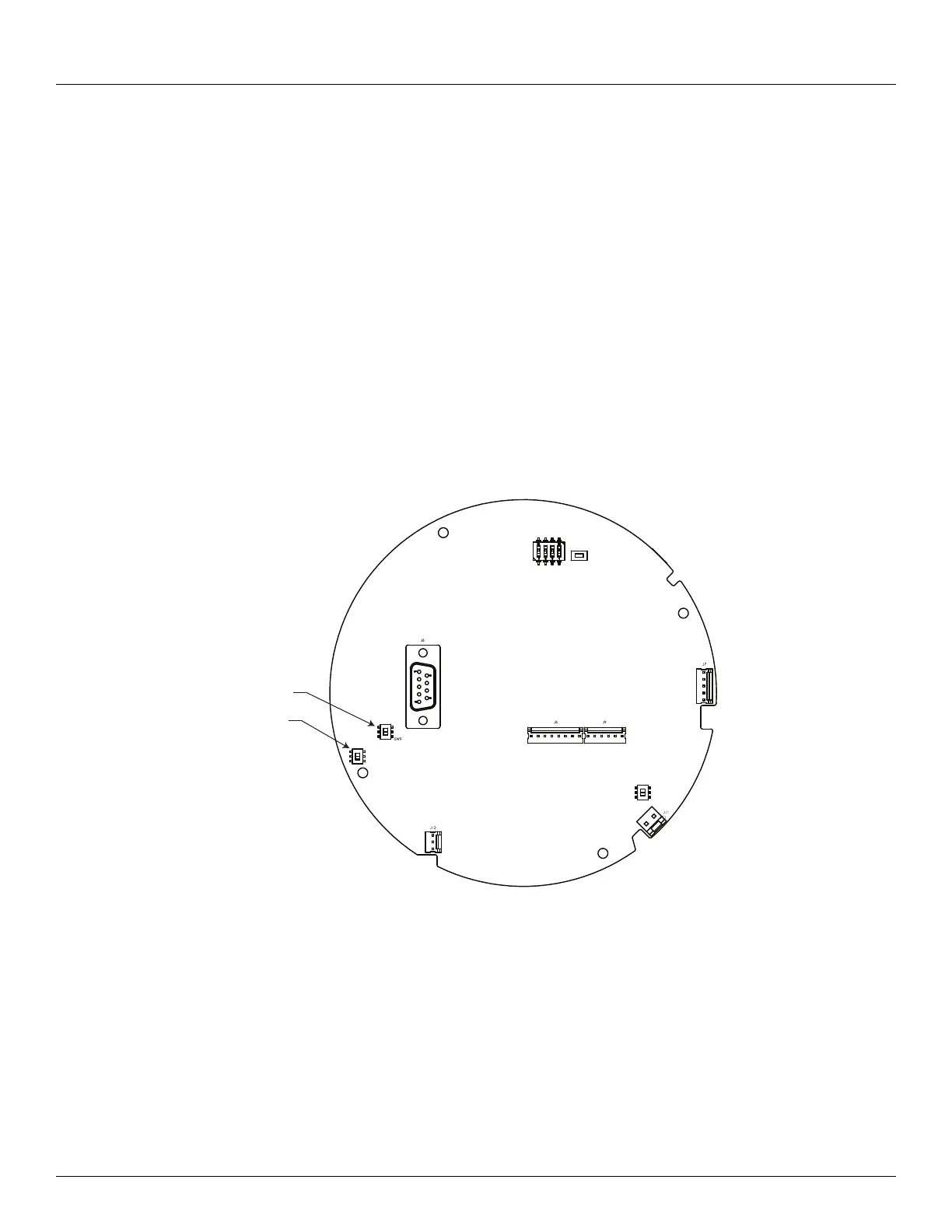
The MODBUS communications board (top shown) appears below:
Terminating the MODBUS Network
In an EIA485 network, devices at each end of the communications network are typically
terminated. In typical installations, these devices are the MODBUS host interface device and
the transmitters with the greatest amount of cable between the transmitter and the host. The
user can terminate the network at a 2920 FTT by closing a switch to apply a 120-ohm resistor
across the network line. This switch is normally set in the UNTERM position.
Note Typically, a terminating resistor is not needed for MODBUS networks operating at
a baud rate below 9600.
SW1
SW6
SW2
RESET
A
UNTERM
TERM
SW8
P
UNBIAS
BIAS
SW9
SW8