4 Wiring
Varec, Inc. 45
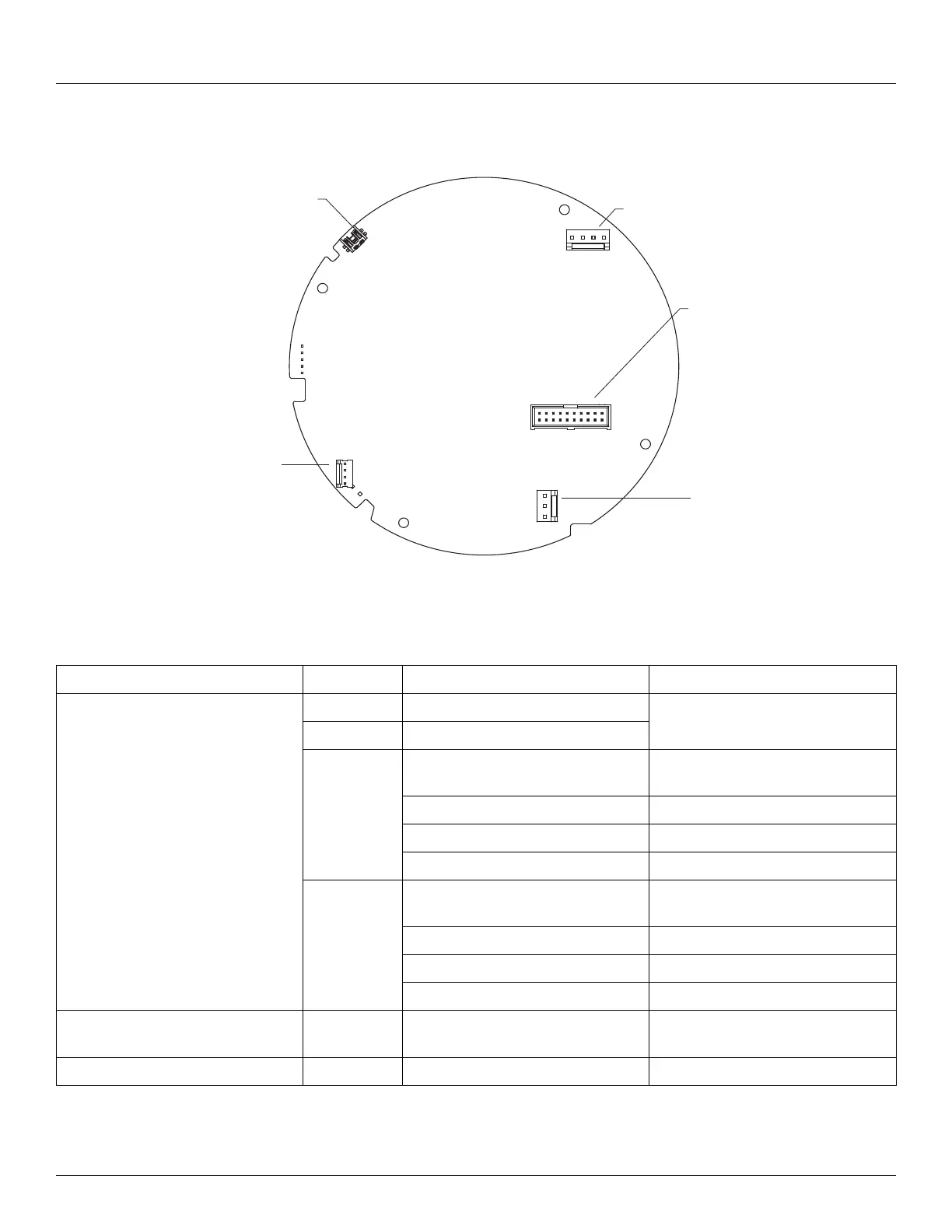
The following figure shows the Communications Board connectors, as viewed from the
bottom. The Bi-Phase Mark board is shown.
Connector Assignments: Communications Circuit Board
J17
J18
J13
J15
J14
J14
J17
J15
J13
J18
Connector / Function Terminal Assignment Description
J13 – DC Power & Communications 1 B- DC Power Negative Terminal All DC Power Transmitters
2 B+ DC Power Positive Terminal
3 Bi-Phase Mark Communications 1 Bi-Phase Mark Communication
Option
+ TX1/ + RX (A) EIA-485 MODBUS
Mark Mark/Space
TankWay Encoder (TXD)
4 Bi-Phase Mark Communications 2 Bi-Phase Mark Communication
Option
- TX/ - RX (B) EIA-485 MODBUS
Space Mark/Space
TankWay Computer (RXD)
J15 – AC Power & Digital I/O Board Connection to Optional AC Power &
Digital I/O Board
J14 – Mini USB Varec Use Only