2920 Float & Tape Transmitter 4 Wiring
34 Installation and Operations Manual
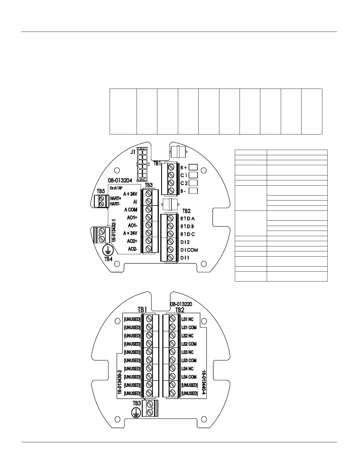
Product Order Code: N2920-aa-1-cc-2-e-1-g-h-i
The following terminals apply to a 2920 FTT with DC power, 4 limit switches, 2 digital inputs,
and optional analog input/analog outputs. Other product options can be variable as shown in
the table below.
N2920
AT
FC
FM
1
BP
MB
MS
LJ
2
A
B
C
D
E
F
1
A
B
C
0
1
A
B
C
Digital Display and
Main Junction Box
Terminal Board Abbreviation Legend:
A COM Analog Common
AI Analog Input
AOx Analog Output
A +24V Analog +24 Volt Power
Output
B+ Power +
B- Power -
Interchangeable
MODBUS: -TX/-RX
Space
TankWay: Computer (RXD)
C2 Bi-Phase Mark:
Interchangeable
MODBUS: +TX/+RX
Mark
TankWay: Encoder (TXD)
D I x Digital Input x
D I COM Digital Input Common
HART+* + Ex d HART (Non-I.S.)
HART-* - Ex d HART (Non-I.S.)
LSx NC Limit Switch Normally
LSx COM Limit Switch Common
R T D x Resistance Temperature
Detector x
* See the I.S. HART Junction Box section for
I.S. HART terminals, when I.S. HART option
is selected.