2920 Float & Tape Transmitter 4 Wiring
44 Installation and Operations Manual
Connecting Wiring in the Transmitter
All standard electronics for the 2920 FTT are contained on the main communications circuit
board. This includes 20-65 VDC power, field communications, 3-wire temperature input, and
two discrete inputs. An optional secondary circuit board contains an AC power supply with
three voltage ranges, two additional discrete inputs, and four discrete outputs. See “Input
Power” and “Selecting the AC Voltage Setting” for more information.
All wiring is terminated in junction box(es). A standard application requires one junction box
for communications, temperature, two discrete inputs. Depending on the order code, multiple
junction boxes may be attached to the transmitter housing.
To connect wires to the electronics assembly, refer to previous sections for connector
locations, terminal assignments, and special instructions.
Warning! Obtain a hot permit before removing the transmitter cover with power
applied.
Note Earth Ground terminals are located on the terminal circuit board in each junction
box. Ensure the external ground is connected.
Caution! Signal wiring connected in this box must be rated at least 300V.
Attention! Le cablage de signalisation raccorde dans cette boite doit convenir pour une
tension nominale d'aumoins 300 V.
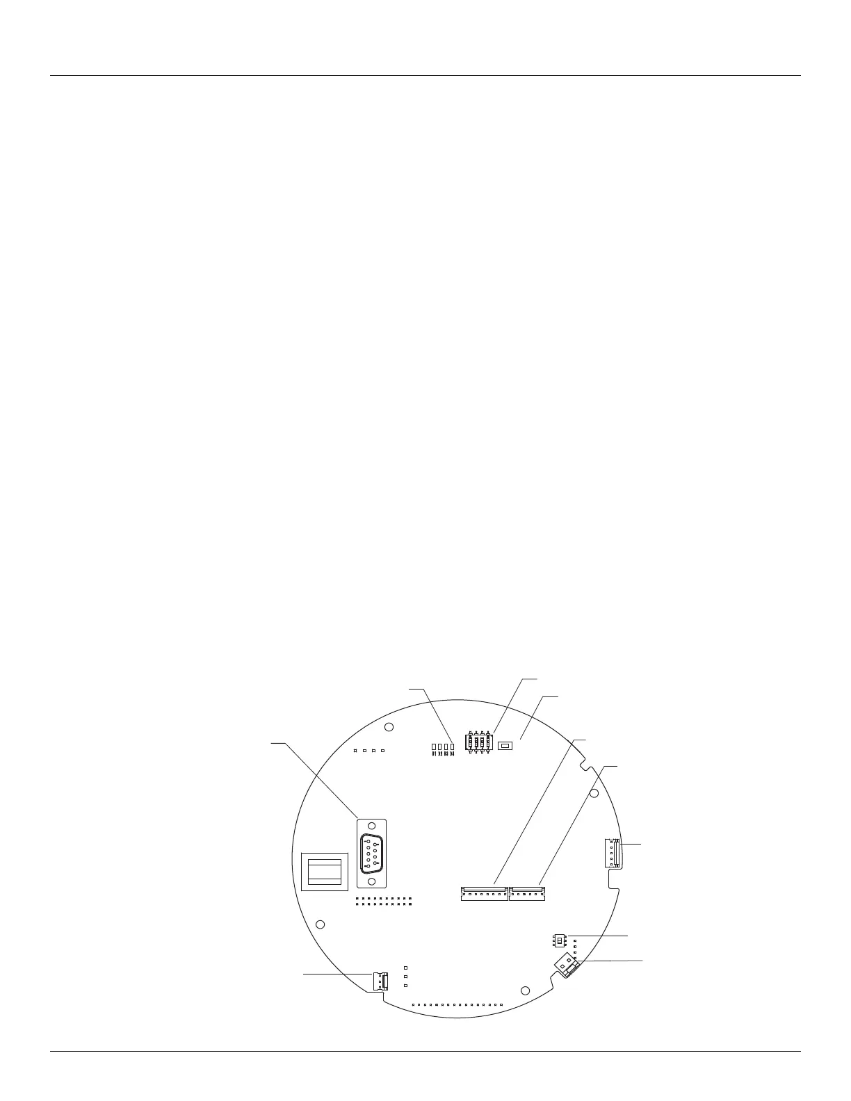
Connector Locations: Communications Circuit Board
The following figure shows the Communications Board connectors, as viewed from the top.
The Bi-Phase Mark board is shown.
RESET
LED
SW1
J6
J8
SW6
J9
J7
J12
J11
SW2
J6
RS-232
J12
SW6
J11
J7
J9
J8
Reset SW2
SW1
LED D4