2920 Float & Tape Transmitter 11 Configuration & Calibration — Level, Limits, and Outputs
124 Installation and Operations Manual
7. After adjusting the dwell, verify that the level that the limit switch activates did not
change.
8. Repeat steps 3 through 7 for each of the remaining limit switches.
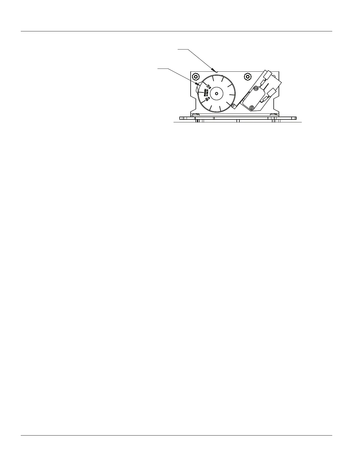
9. Rotate the 2920 FTT encoder shaft until the correct level reading (matching the gauge) is
displayed by the local display.
10. Tighten the coupling on the transmitter drive shaft.
11. Replace the transmitter cover.
Configuring Outputs
To configure outputs for the 2920 FTT use the local display interface or the user must connect
a laptop computer running the ViewRTU software to the RS-232 port. Then use ViewRTU to
define alarm conditions and to assign a condition to each output. For the Bi-Phase Mark 2920
FTT, the outputs can also be configured through the Bi-Phase Mark interface by writing data
items using the appropriate commands.
Warning! Obtain a hot permit before removing the transmitter cover with power
applied.
Note For more detailed information regarding the ViewRTU program, refer to any Varec
RTU Installation and Operation manual.
To Configure Outputs:
1. Using the local display: Digital Outputs> Config Params.
Optionally, you can use the Bi-Phase Mark host system.
Note For more information and specific details for configuring Digital Outputs, see “Dig-
ital Outputs”.
2. For the Bi-Phase Mark 2920 FTT, you can use the Bi-Phase Mark interface to configure the
outputs by writing data using the appropriate item command.
Optionally, use ViewRTU as follows:
Warning! Obtain a hot permit before removing the transmitter cover with power
applied.
Notch Indicator
Dial Indicator