5 Display and Configuration Interface
Varec, Inc. 55
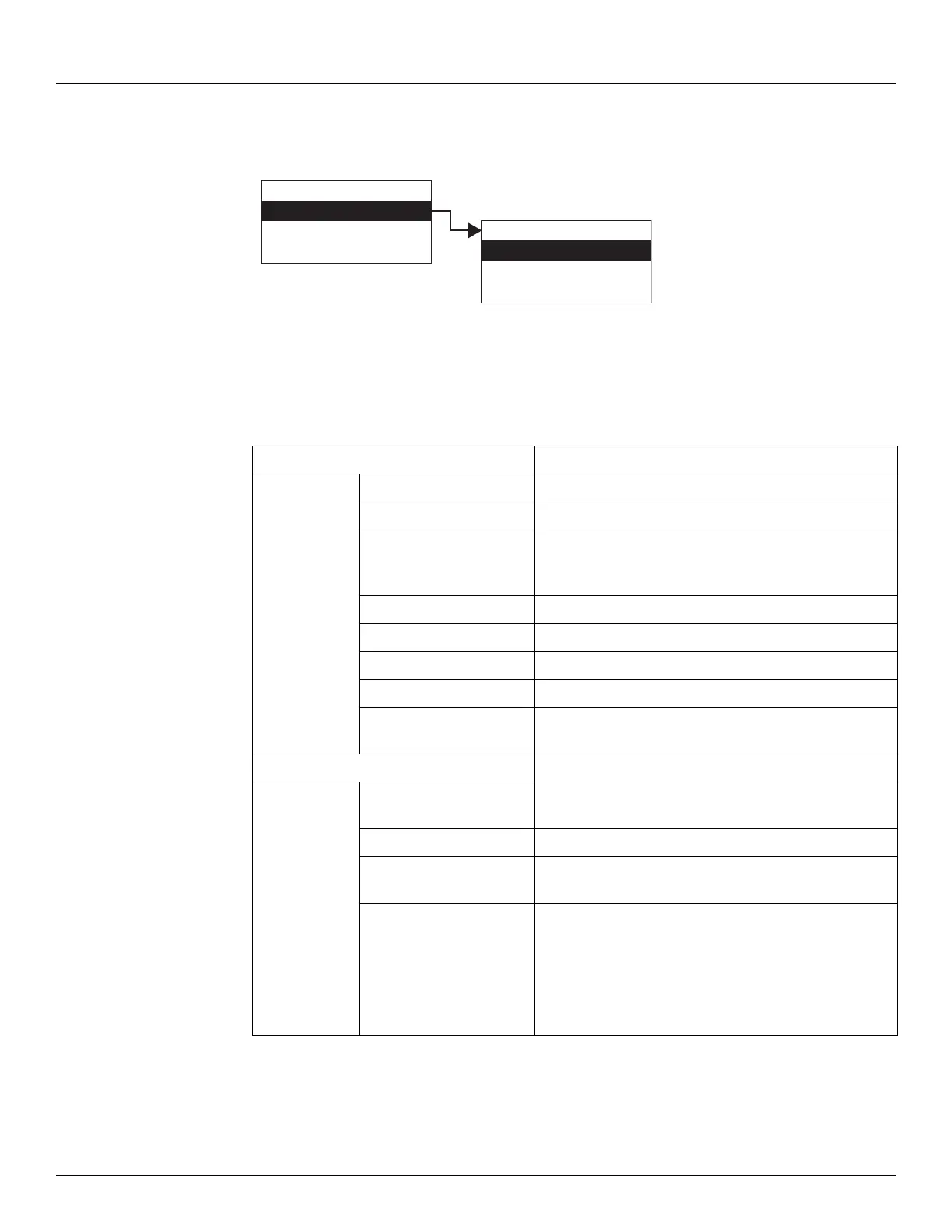
To Access the System Data:
1. Press Enter to access the Main Menu. The System Data point is automatically highlighted.
2. Press Enter to open the System Data parameters and the System Data options appear.
3. To select one of the options, press Minus to move the highlight to the option you want and
then press Enter.
4. Refer to the table below for more information on each System Menu option.
Display Only Description
Software Version The firmware version.
Hardware Version The PCB hardware version.
Field Protocol Specifies the type of the interface hardware available
for the primary interface, such as Bi-Phase Mark,
MODBUS, Mark/Space, and so on.
Number DB Pnts The number of database points defined.
DB Size The size of the database in bytes.
Build Date The date the database structure was generated.
Sys Checksum CRC-16 Checksum of the firmware.
Pnt Checksum CRC-16 Checksum of point's static configuration
parameters.
Commands Description
Admin PIN Allows you to set the administrative PIN code. See
“Administrative PIN”.
User PIN Allows you to set the user PIN code. See “User PIN”.
Display Test The Display test temporarily illuminates all segments of
the graphical display to test the operation of the display.
Reset Cmd The Reset Command allows reset of the transmitter
through the user interface. A soft reset restarts the
application. A hard reset resets all configuration data to
default values.
Note Be careful not to perform a hard reset inadver-
tently.
Display Only
Commands
Config Params
All Params
Main Menu
System Data
Basic Setup
Local RS-232
00
System Data