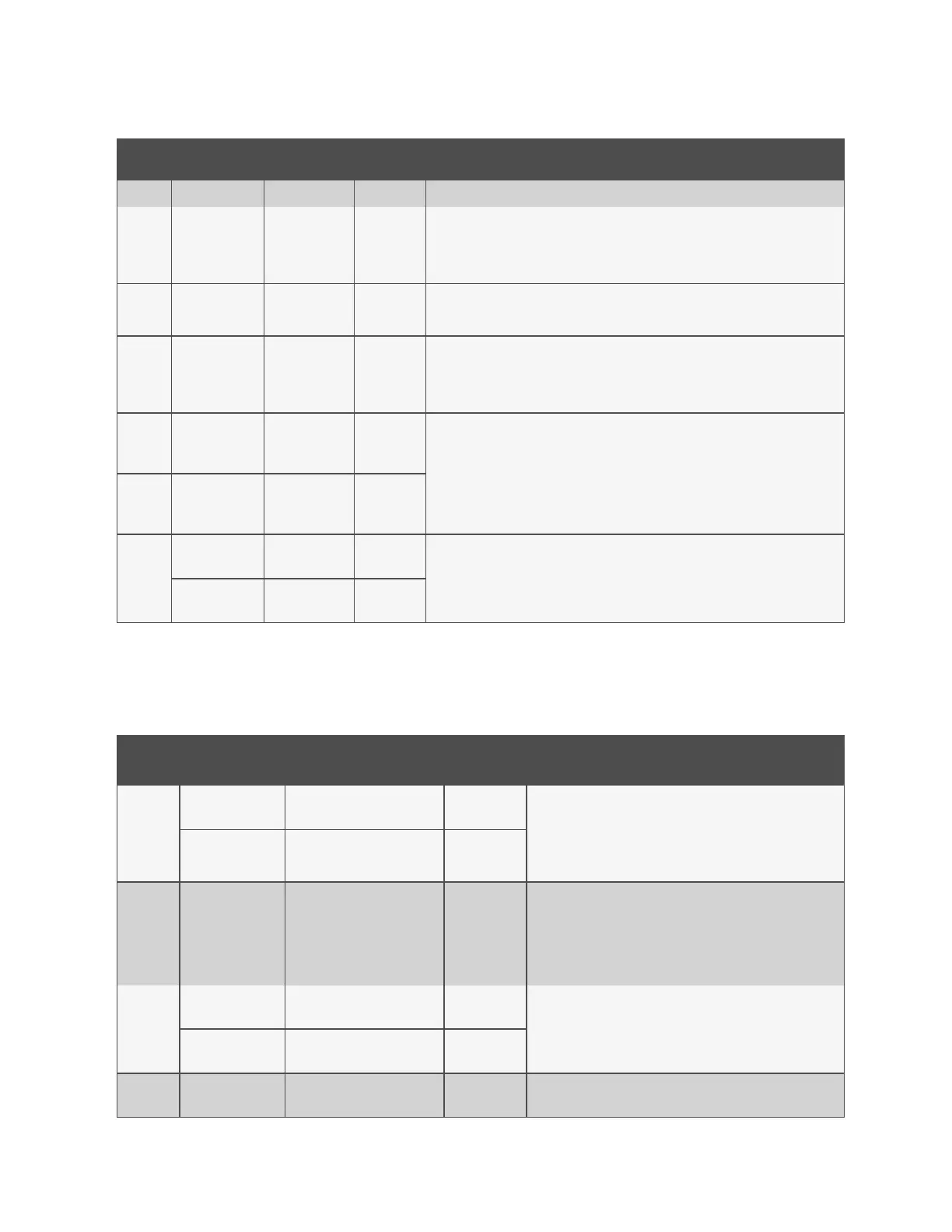
Line
ID
Parameter
Name
Range
Default
Setting
Description
Integration Time stable control.
S150.1
Fan Hysteresis 0 - 20% 0.02
Modifies the reaction of the fan speed when fan speed is being dictated by the Call for
Cooling. Adding the Hysteresis may result in a lagged response to changes in fan
speed.
S150.2 Fan Deadband
0 - 36°F
0 - 20.0 K
°F
0.6 K
Avoids overshooting of the setpoint. The value entered in this field will be split in half by
the fan speed setpoint.
S151.1
Airflow
Calibration
3.0 - 10.0 V 10.0 V
Allows the front display to be scaled to show the actual percentage of airflow
independent of the voltage operating the fan speed. This value cannot be set
above/below the Analog Output High/Low Limit for the fan set in the Advanced Menu.
This also includes the service menu fan speed parameters.
S152.1
Fanspeed VSD
Setpoint
Minimum
0 - 100% 0.7
Sets the range for the variable fans. Min sets the minimum speed at which the fan will
operate. Fan speed is modulated between MIN and STD based on which sensor is set as
the controlling sensor, setpoint and the PI settings. If the controlling sensor is set to
manual, then the STD setting will control the current fan speed. This parameter is also
adjustable through the BMS.
S152.2
Fanspeed VSD
Setpoint
Standard
0 - 100% 1
S157
Fan Startup
Time
0 - 600 sec 3 sec
Determines the speed of the fan at system start up. The fan will operate at the set
speed (%) until the set time has elapsed; at this point the fan will assume normal
operation.
Fan Startup
Speed
0 - 100% 100%
Table B.1 Service Menu Setpoints by Line ID (continued)
B.2 Line IDs for Alarm Setting Parameters
Line
ID
Parameter
Name
Range
Default
Setting
Description
S202
Return Sensor
Alarms Enable
Disabled Enabled Enabled
Enables or disables the return temperature and humidity sensor
alarms.
Return Sensor
Alarms Init Delay
10 - 9999 sec 90 sec
S203
High Return
Temperature Alarm
34 - 210 °F
1.0 - 99.0 °C
100 °F
Sets the temperature threshold for the high/low return
temperature alarms.
Low Return
Temperature Alarm
34 - 210 °F
1.0 - 99.0 °C
65 °F
S204
High Return
Humidity Alarm
1.0 - 99.0 % 0.65
Sets the humidity threshold for the high/low return temperature
alarms.
Low Return
Humidity Alarm
1.0 - 99.0 % 0.35
S205
Sensor A Alarms
Enable
Disabled Enabled Disabled
Enables or disables the alarms associated with Sensor A and sets
the time delay before the alarm is annunciated.
Table B.2 Service Menu Alarm Settings by Line ID
208
Vertiv™ Liebert® iCOM™Installer/User Guide