Vertiv™ | Liebert® SRC-G | User Manual
29
Mechanical Installation
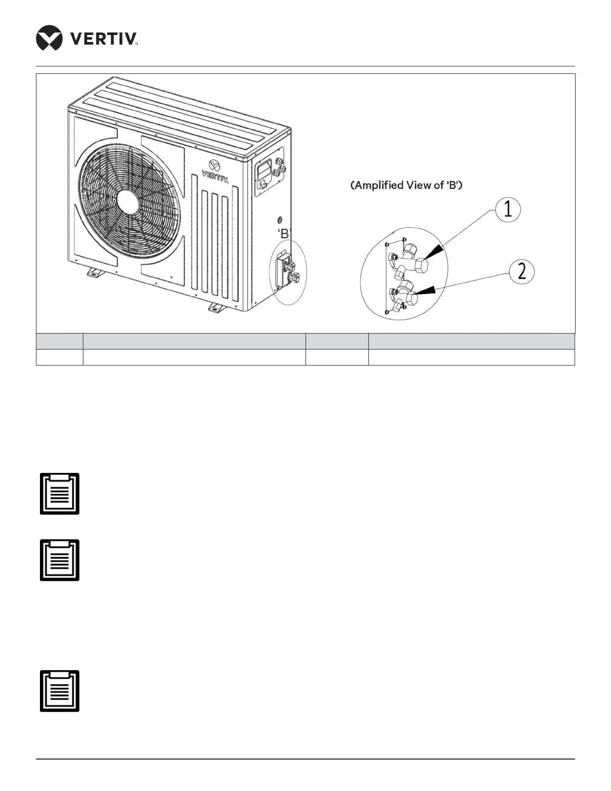
No. Description No. Description
1 Gas (Suction) pipe 2 Liquid (Discharge) pipe
Figure 2-16 Pipeline Connector Interface (Outdoor Unit)
• Connecting Gas (Suction) pipe
Connect one end of the gas pipe connector of the indoor unit shown in Figure 2-15 to the other end of the gas
pipe connector of the outdoor unit shown in Figure 2-16.
The gas pipe is the pipe at the compressor discharging side. Horizontal sections of the liquid pipe should be
sloped down from the compressor with a slope of at least 1:100 (10 mm down for each 1 m run). The gas pipes
should be insulated where they are routed in the conditioned space.
As indoor unit is charged with Nitrogen (30 psi) pressure, release the Nitrogen safely in the atmosphere.
• Connecting Liquid (Discharge) pipe
Connect one end of the liquid pipe connector of the indoor unit shown in Figure 2-15 to the other end of the liquid
pipe connector of the outdoor unit shown in Figure 2-16.
Ensure service valve of outdoor unit are firmly close during piping connection, as the outdoor unit is
pre-charged with refrigerant equivalent to 10 m piping, refer Figure 2-11 for pre-charged details.