Vertiv™ | Liebert® SRC-G | User Manual 41
Electrical Installation
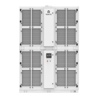
Figure 3-7 shows the networking of the two Liebert SRC-G units monitored through the Vertiv RDU-A/
SIC monitoring.
Figure 3-7 Monitoring the Networking of Two Liebert® SRC Units.
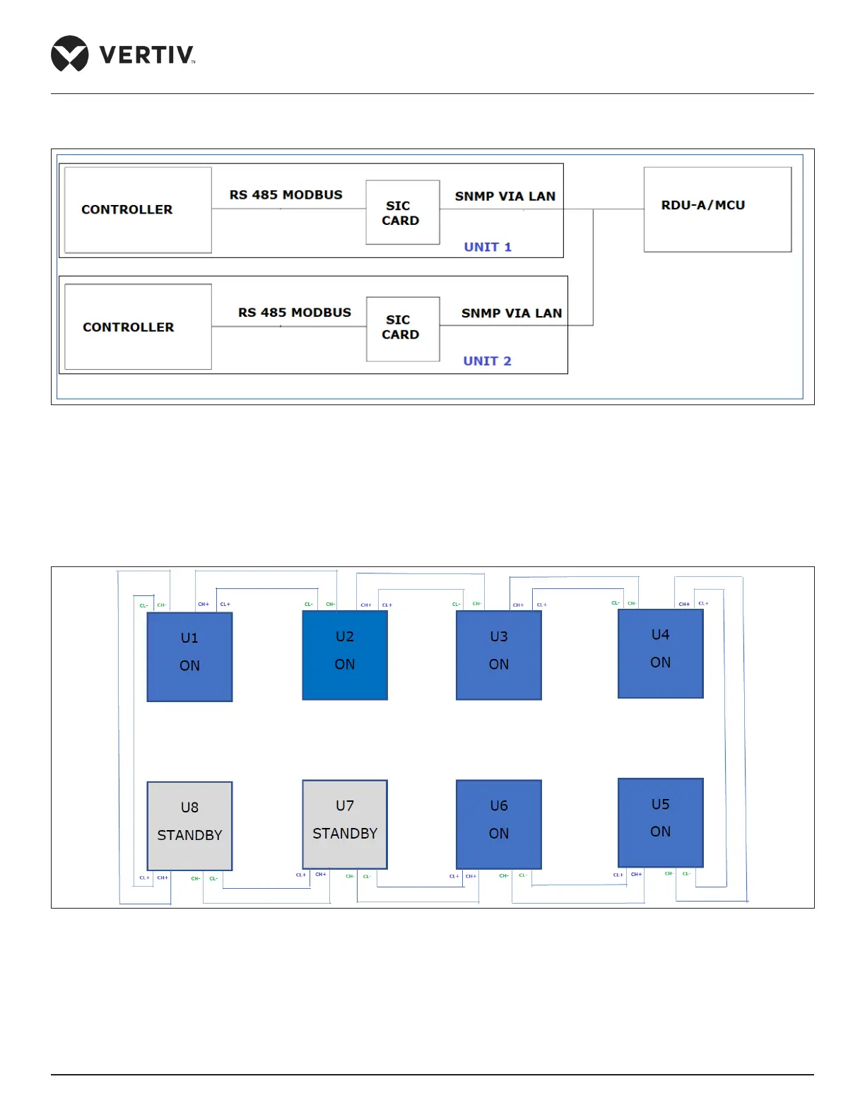
• Teamwork/Sequencing connection
Vertiv™ Liebert® SRC-G units support the teamwork control function of up to 8 units. If user needs to use the
teamwork control function, then connect the teamwork control terminals SEQ CH+, SEQ CL+, SEQ CH- and
SEQ CL- between the units in series.
Figure 3-8 Connection Diagram of Teamwork Control Terminal
Refer Figure 3-8 for cabling the units, after the teamwork control unit is cabled, set jumper on CONN 2 connector
in control panel between J33: 1 & J33: 2 for first and last unit and set between J33: 2 & J33: 3 for rest of the units.
The maximum allowed network cable length of 400 m.