Vertiv | NetSure 7100 Series -48V DC Power System Installation Manual (IM582127000) | Rev. BB
External Alarm, Reference, Monitoring, and Control Connections
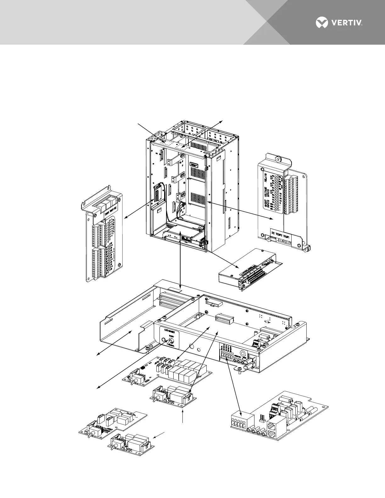
Circuit Card Locations
Refer to Figure 59.
Figure 59:
Circuit Card Locations (Main Bay)
Optional SM-DU+ and
Shunt Interface Board
4-Row Cabinet Shown,
Others Similar
(Front Door Removed in
Illustration for Clarity)
Controller
System Interface
Circuit Card
OR
Optional LVD
Driver Circuit Card
Optional LVD
Inhibit Switch
(factory installed
if option specified)
Optional LVD Driver
Lite Circuit Card
Optional Manual Battery
Disconnect Circuit Card
(Main Bay Only)
IB2 (Main Bay Only)
(Interface Board)
(located on inside side panel)
Optional EIB (Main Bay Only)
(Extended Interface Board)
(located on inside side panel)
Optional IB4 (Main Bay Only)
(Second Ethernet Port Board)
Optional Second IB2 or EIB (Main Bay Only)
(underside of cover)

 Loading...


