Vertiv | NetSure 7100 Series -48V DC Power System Installation Manual (IM582127000) | Rev. BB
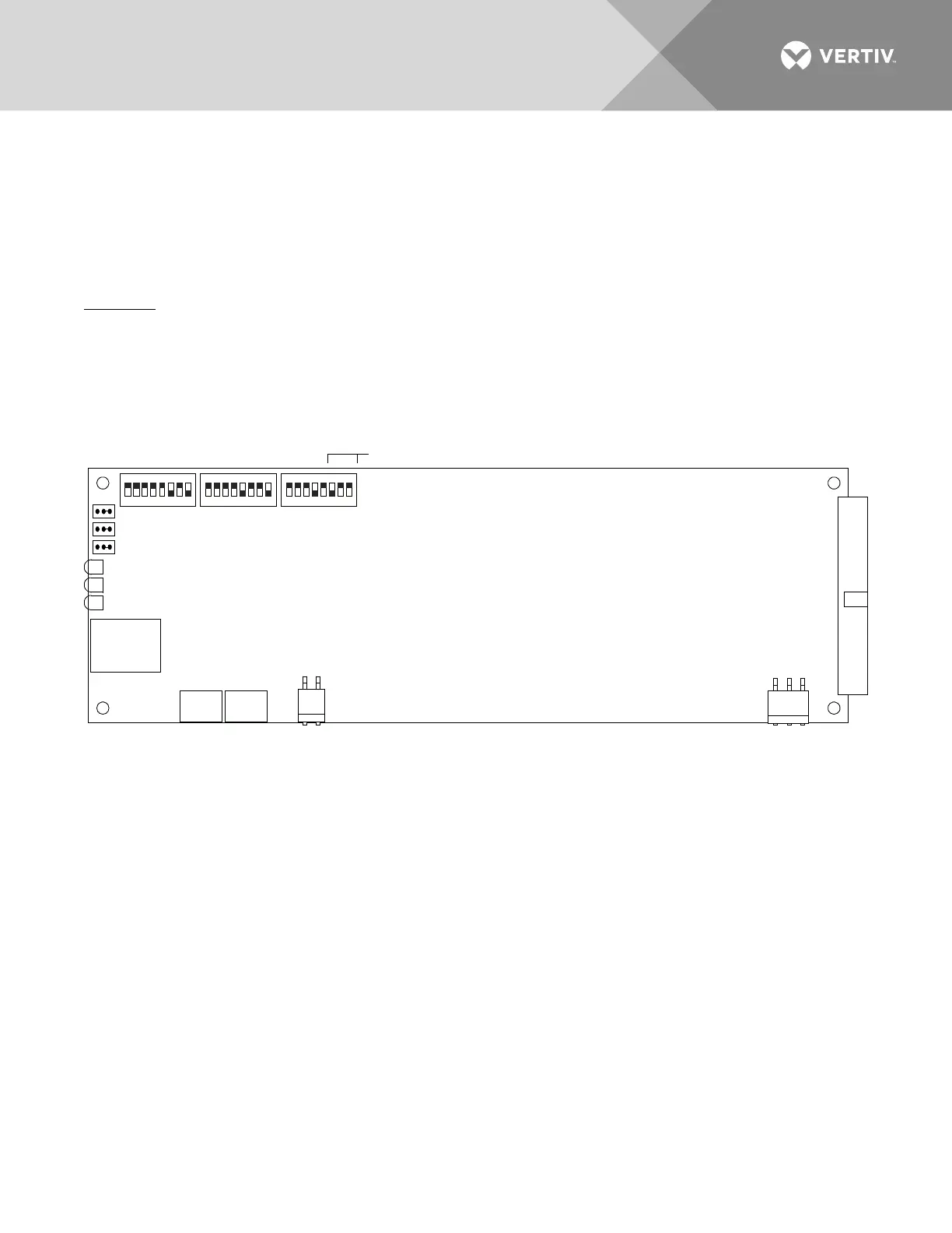
Switch Setting on SM-DU (Supplemental Bays Only)
SM-DU uses three (3) 8-bit switches for parameter setting (S1, S2, and S3). Refer to Table 3for switch settings.
Refer to Figure 35 for switch locations.
Perform the following procedure to verify the factory settings. This procedure can also be used to make
adjustments on a replacement circuit card.
Procedure
1. Ensure S1, S2, and S3 are set per Table 3. Refer to Figure 35 for location.
Figure 35:
SM-DU Switch Location
Supplemental
Bay Addressing
8 7 6 5 4 3 2 1 8 7 6 5 4 3 2 1 8 7 6 5 4 3 2 1
SM-DU Circuit Card
S 1S2S3
JP1
JP2
JP3
J5
J4J4A
J3
J1
J2
Power
CANRS485
R
S
48
5
RS232
ON
OFF
Green Indicator (Operation)
Yellow Indicator (Alarm)
Red Indicator (Alarm)

 Loading...


