Vertiv | NetSure 7100 Series -48V DC Power System Installation Manual (IM582127000) | Rev. BB
Checking System Status
Procedure
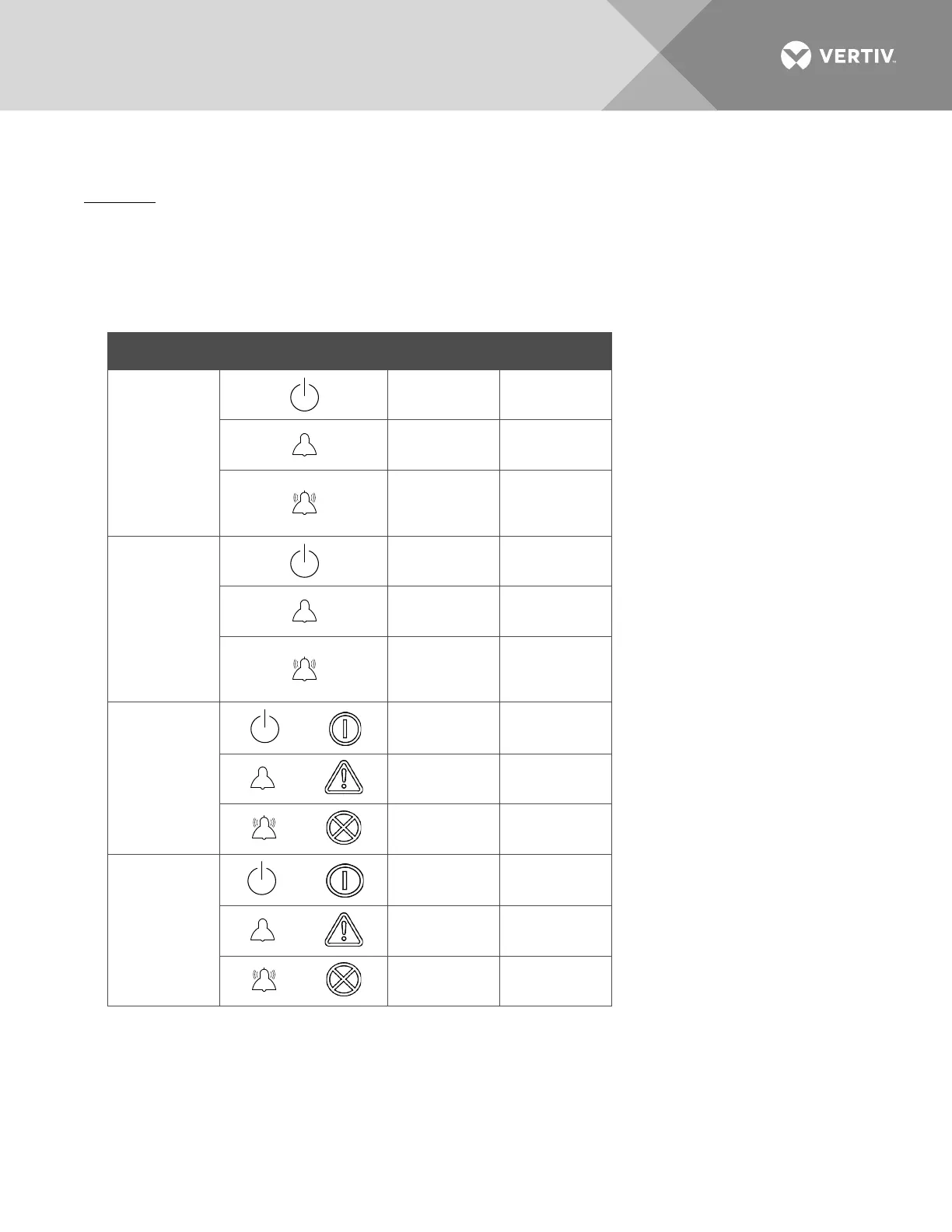
1. Observe the status of the indicators located on the controller, rectifiers, and converters (if furnished). If
the system is operating normally, the status of these is as shown in Table 16.
Table 16:
Status and Alarm Indicators
Component Indicator Normal State
ACU+
Status
(Green)
On
Minor
(Yellow)
Off
Critical or
Major Alarm
(Red)
Off
NCU
Status
(Green)
On
Minor
(Yellow)
Off
Critical or
Major Alarm
(Red)
Off
Rectifier
Modules
or
Power
(Green)
On
or
Protection
(Yellow)
Off
or
Alarm
(Red)
Off
Converter
Modules
or
Power
(Green)
On
or
Protection
(Yellow)
Off
or
Alarm
(Red)
Off

 Loading...


