Vertiv | NetSure 7100 Series -48V DC Power System Installation Manual (IM582127000) | Rev. BB
Switch Setting on SM-DU+
SM-DU+ uses two (2) 8-bit switches for parameter setting (SW1 and SW2). Refer to Table 4 for SW1 and SW2
settings. Refer to Figure 36 for SW1 and SW2 locations.
Perform the following procedure to verify the factory settings. This procedure can also be used to make
adjustments on a replacement circuit card.
Procedure
Ensure SW1 and SW2 are set per Table 4. Refer to Figure 36 for location.
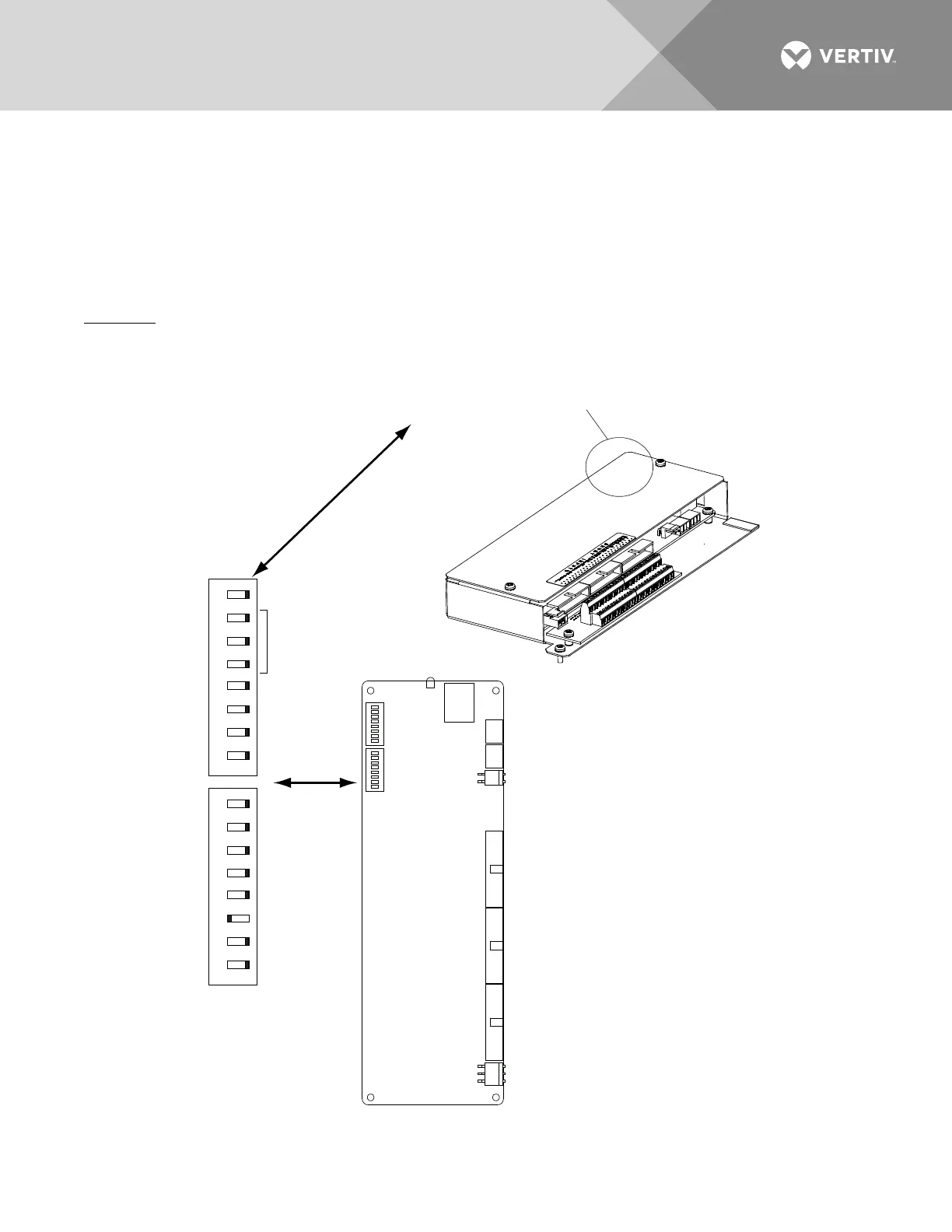
Figure 36: Optional SM-DU+ Switch Location and Settings
SM-DU+ and
Shunt Interface Board
SM-DU+
Switches SW1 and SW2 are located
in this corner of the SM-DU+.
SW1 SW2
on
5 6 7 8
1 2 3 4
off
on
5 6 7 8
1 2 3 4
off
SW1 and SW2
In this system, switch settings
must be in the positions shown,
except adressing switches, which
must be set to a uniqe address.
Set each SM-DU+ in
the system to a unique
address.
Power CAN RS485 RS485
RS232
SW1 SW2
J1
J7
Shunt Shunt
J8 J6
Fuse
J3
J4 J4A
J5
ON
OFF
1 2 3 4 5 6 7 8 1 2 3 4 5 6 7 8
Green Indicator

 Loading...


