Vertiv | NetSure 7100 Series -48V DC Power System Installation Manual (IM582127000) | Rev. BB
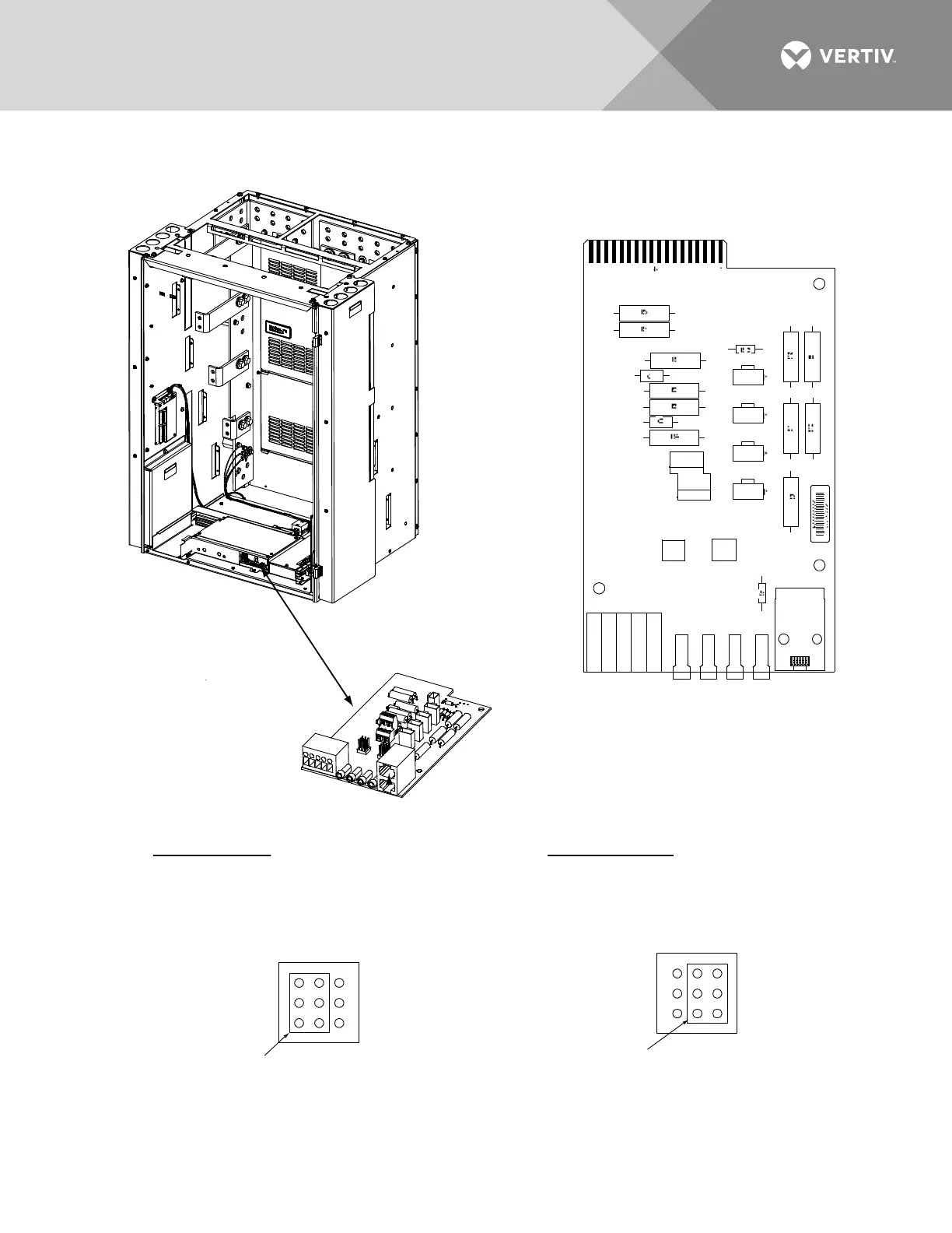
Figure 32:
System Interface Circuit Card Jumper Locations
Switch Settings on IB2 Interface Board (Main Bay Only)
Dip Switch SW1 on the IB2 board is used to set the communications address for this board. Refer to Table 1 for
SW1 settings. Refer to Figure 33 for SW1 location.
1
1A
2A 3A
1B 2B 3B
5
J1
J2
J3
J4
J8
TB2
TB1
TP1 TP2 TP3 TP4
J10
J5
TB1-2, TB1-3, TB1-4, TB1-5 Main Bay Only.
TB1-4: External Battery Monitoring (-)
TB1-5: External Battery Monitoring (+)
4-Row Cabinet Shown,
Others Similar
(Front Door Removed in
Illustration for Clarity)
System Interface
Circuit Card
System Interface
Circuit Card
External Internal
J10
1
2
3
7
8
9
J10 (Main Bay Only)
Battery Monitoring External / Internal
(see TB1-4 and TB1-5 for
external monitoring points)
Shorting Jumper
J8 (Main Bay Only)
Selects to power Controller
from “Battery Power” or not.
No
Battery
Pwr
Battery
Pwr
J8
1
2
3
7
8
9
Shorting Jumper
Main Bay Only.

 Loading...


