Vertiv | NetSure 7100 Series -48V DC Power System Installation Manual (IM582127000) | Rev. BB
Installing Optional Battery Busbar Extension Kit, Part No. 562364
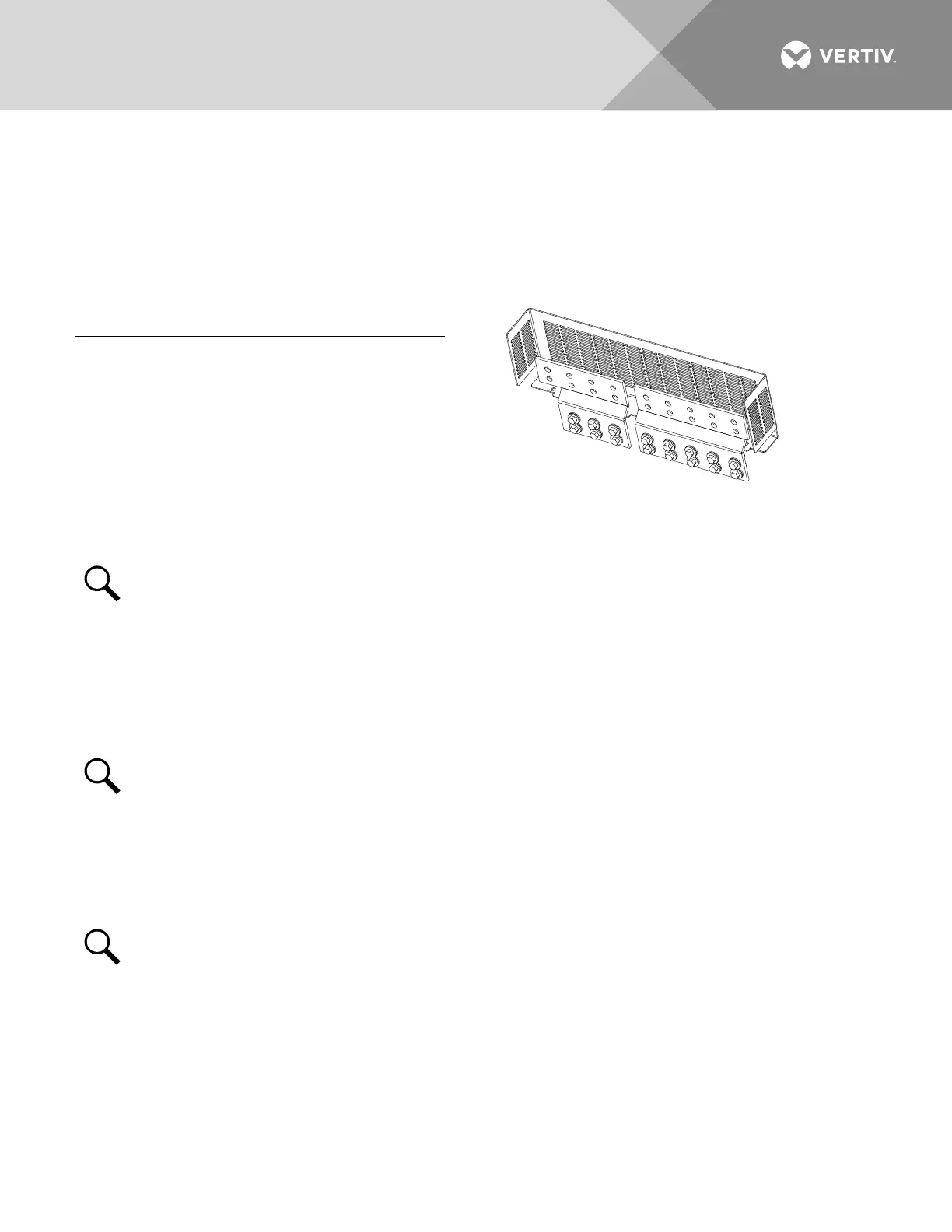
This kit provides plates that extend the system busbars above the top of a List 23 and List 24 distribution
cabinet and increases the number of lug landings available for battery cables. This kit provides back-to-back
landings for up to ten lugs for the hot side and eight lugs for the return side.
Installing Part No. 562364 Busbar Extension Kit
This kit consists of the following:
Return Side Extension Busbar
Power Side Extension Busbar
Perform the following steps to install the battery busbar extension plates.
Procedure
NOTE!
Refer to
Figure 19
as the procedure is performed. A system installed in a relay rack is shown in
the illustration. The procedure for a system installed in an enclosure is the same except as noted in the
following procedure steps.
1. Open the distribution cabinet’s front door by turning the latch in the counterclockwise position
(system’s in a relay rack), or open the system’s enclosure door.
2. Install busbar extension plates as shown in Figure 19. Apply anti-oxidizing compound to busbar mating
surfaces before assembling. Tighten bolts to the recommended torque value shown in Figure 19.
NOTE!
Install the Belleville lock washers so the concave side is towards the busbar.
3. Close the distribution cabinet’s front door and turn the latch clockwise to secure the door (system’s in a
relay rack), or close the system’s enclosure door.
Perform the following steps to mount the Lexan cover.
Procedure
NOTE!
Refer to
Figure 20
as the procedure is performed. A system installed in a relay rack is shown in
the illustration. The procedure for a system installed in an enclosure is the same except as noted in the
following procedure steps.
1. Loosen the four (4) screws at the back of the busbars.
2. Place the Lexan cover at the back of the busbars and use the four (4) screws to secure it.
3. Remove the four (4) screws at the top of the enclosure and place the cover.
4. Re-use the screws to secure the top cover.

 Loading...


