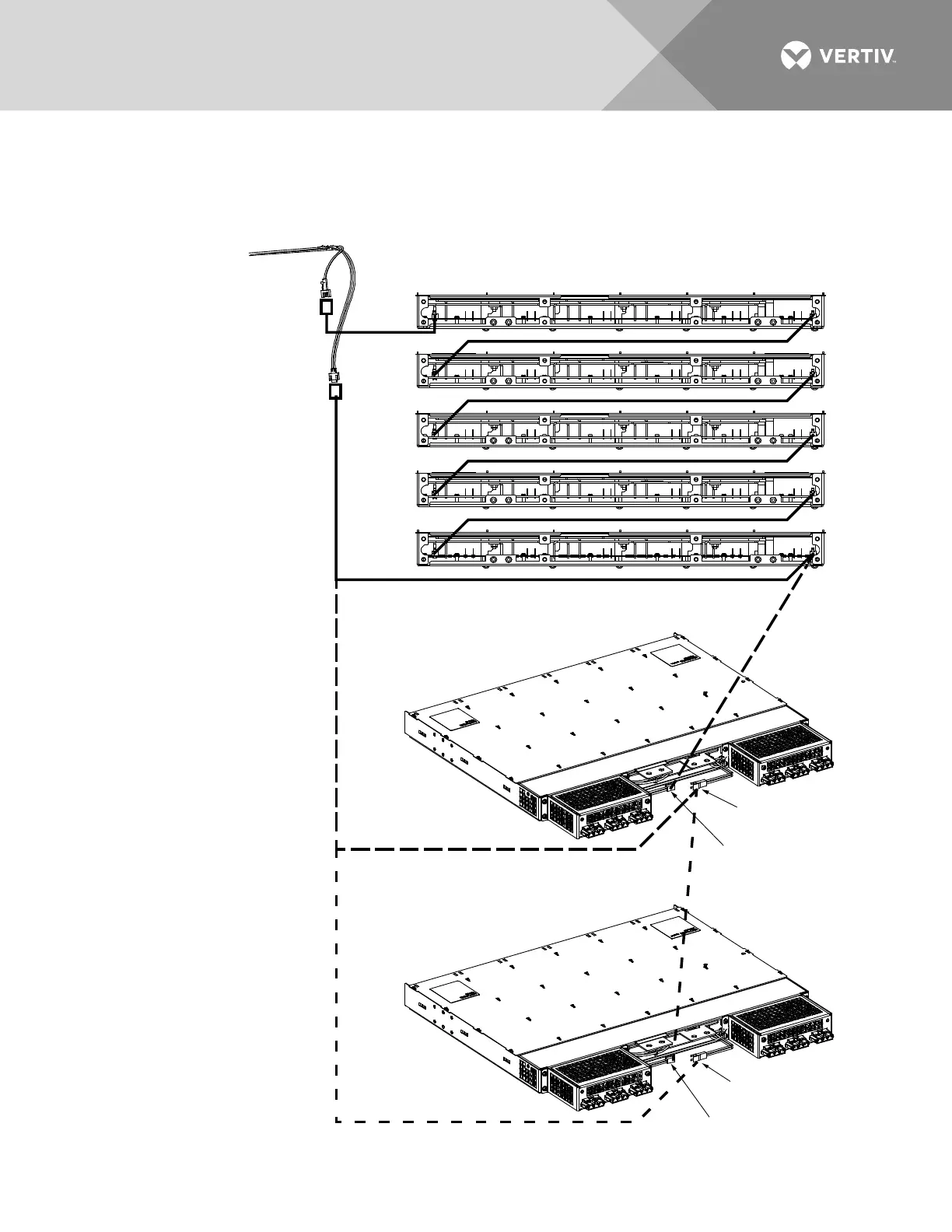
Exploded V
iew Shown to
Illustrate Wire Connections
Only. Covers Not Shown.
Adding First Expansion Shelf:
Disconnect cable 562086 from
right rear connector of bottom-most
existing shelf, then connect cable
562086 to cable BMY200005/1 in
center section of expansion shelf.
Then connect cable BMY200004/1
in center section of expansion
shelf to right rear connector in
bottom-most existing shelf.
Adding Second Expansion Shelf:
Disconnect cable 562086 from
cable BMY200005/1 in center
section of first expansion shelf,
then connect cable 562086 to
cable BMY200005/1 in center
section of second expansion shelf.
Then connect cable BMY200004/1
in center section of second
expansion shelf to cable
BMY200005/1 in center
section of first expansion shelf.
Distribution
Cabinet Wire
Harness
BMY200004/1
562087
Factory CAN Bus Wiring (Five 588705400 List 01 Shelves)
Adding First
Expansion Shelf
(588705400 List 02,
03, or 04)
BMY200004/1
BMY200004/1
BMY200004/1
Factory Installed
BMY200004/1
Factory Installed
BMY200005/1
562086
Adding Second
Expansion Shelf
(588705400 List 02,
03, or 04)
Factory Installed
BMY200004/1
Factory Installed
BMY200005/1

 Loading...


