Theory of Operation Mobile Generator
wc_tx001077gb.fm 20
• Since the legs are mechanically 120° apart, as the rotor spins, time
elapses between the moment when one leg reaches its largest volt-
age potential and the moment when the next leg reaches its largest
voltage potential. Thus, no two legs reach their largest voltage poten-
tial at the same moment in time, and their corresponding sine waves
are 120° apart. In other words, the voltages induced in each leg are
120° out of phase with each other.
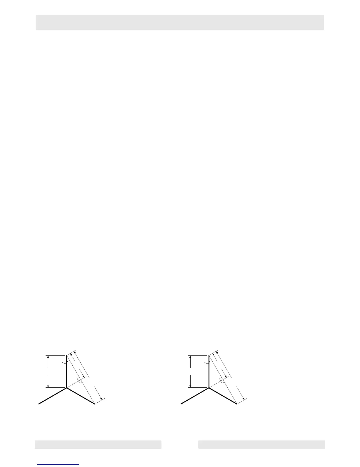
• Although the largest amount of voltage induced in any single leg in
the high-wye configuration is 277V, the voltage induced in a second
leg (either of the other two legs) at that same moment can be tapped
and combined with the 277V of the first leg to create the maximum
voltage available from the generator. The amount of voltage in the
second leg is less than its largest potential because of the position of
the rotor’s magnetic field—it is less than perpendicular to the second
leg. The amount of voltage induced is approximately 73% (203V) of
its potential (see graphic wc_gr003317). Thus, 277V + 203V = 480V,
which is the maximum voltage available from the generator. In the
low-wye configuration, the largest usable voltage potential in any leg
is 120V; adding the 73% of any second leg (88V), yields the maxi-
mum voltage potential for the low-wye configuration—208V.
• Any measurement between the end of a leg and neutral is know as
line-to-neutral (L-N) voltage. Any measurement between the end of
one leg to the end of another leg is known as line-to-line (L-L) voltage.
Any combination of L-N or L-L voltages are 120° out of phase with
each other. For example, L1–N is out of phase with L2–N; L2–N with
L3–N; L3–N with L1–N. Likewise, L1–L2 is out of phase with L2–L3;
L2–L3 with L3–L1; and L2–L3 with L1–L2.
• A three-phase event exists when a three-phase load is attached to the
generator. The three-phase load uses both the voltage and current
from each phase produced by the generator simultaneously. Positive
current produced by the voltage from each leg flows to corresponding
legs of the load.
Sine 60 = 0.866
Sine 60 = a/277
0.866 = a/277
277 x 0.866 = (a/277) x 277
240 = a
2(a) = 480
480 – 277 = 203
203/277 = 0.73 = 73%
30˚
60˚
60˚
120˚
120˚
a
2(a)
wc_gr003317
277
Sine 60 = 0.866
Sine 60 = a/120
0.866 = a/120
120 x 0.866 = (a/120) x 120
104 = a
2(a) = 208
208 – 120 = 88
88/120 = 0.73 = 73%
30˚
60˚
60˚
120˚
120˚
a
2(a)
120
 Loading...