Mobile Generator Theory of Operation
wc_tx001077gb.fm 21
• Wacker Neuson generators are designed to accommodate various
loads and multiple power factors. Power factor is the relationship
between power supplied to the load (referred to as apparent power in
kVA) and true power (power used by the load (kW). It is expressed
mathematically by the equation: power factor = true power ÷ apparent
power. The power factor is determined by the type of load—inductive
or resistive. In resistive loads, such as heaters, the power factor is
typically 1. In inductive loads, such as motors and transformers, the
power factor is always less than 1. In inductive loads, a portion of the
supplied power is converted to a magnetic field and not used by the
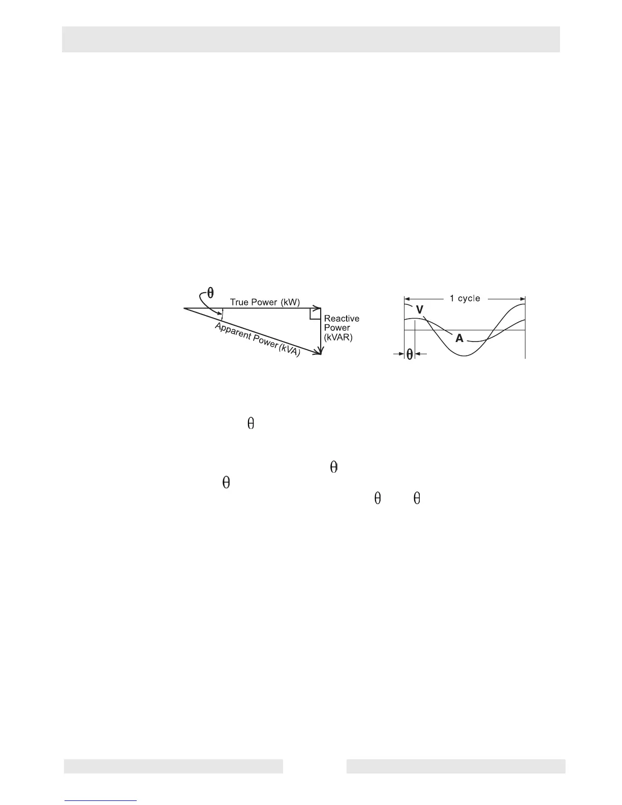
load. This unused power is known as reactive power. The relationship
between apparent power, true power, and reactive power is illustrated
in the power right triangle below.
Reactive power and true power are always represented 90° from
each other. In the power right triangle, the angle formed by the hypot-
enuse (apparent power) and the adjacent side (true power) is referred
to as theta ( ). Theta is derived from the separation in the sine waves
of voltage and current. In inductive circuits, current lags the voltage
due to such factors as coil length, coil material, and frequency. From
trigonometry, the cosine of = adjacent side ÷ hypotenuse. Since
cosine and power factor are calculated in the same manner, power
factor is often referred to as cosine (cos ).
• Single-phase receptacles are tapped off the legs in a manner that
keeps the generator balanced. That is, voltage supplies to the various
single-phase outlets originate from different legs of the generator (L1
and L3), not from the same leg. When tapping single-phase loads
from the lugs, care must be taken so that the generator does not
become unbalanced. Attach equal loads to each leg if you are running
the generator in this manner.
 Loading...