8-36 BA 357-00 * 3.0 * 35700_08_Betriebsstörung.fm
8 Malfunctions
Displays
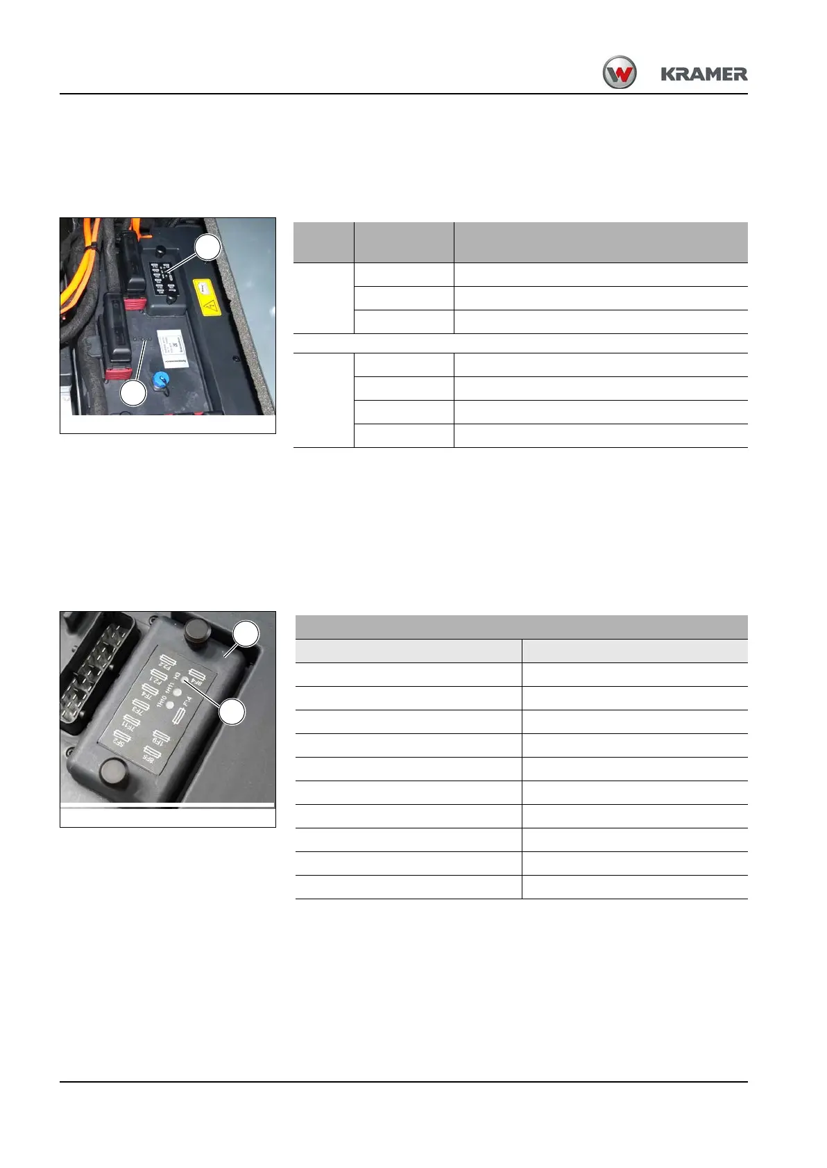
There are 7 LED indicator lights in total located under the operator seat on
the front side of the control. The indicator lights act as a minimal
diagnosis.
Burned out or missing fuses are indicated by means of flash codes via the
diagnosis indicators for fuses H3 and H7.
The flash code is composed as follows: the LED is repeatedly switched
briefly on (approx. 0.2 sec) and off (ca. 0.4 sec). Lastly, a longer pause
follows (approx. 2 sec), indicating the end of the start of the flash code.
The number of times the LED is repeatedly switched off
(e.g. 4 times consecutively off = flash code 4).
Area
Designation
LED
Function
A
1H10 Indicator display travel drive
1H11 Indicator display hydraulic system
H3 Diagnosis indicator fuse box 1
B
H4 Indicator display control
H5 Indicator display interface – part system A
H6 Indicator display interface – part system B
H7 Diagnosis indicator fuse box 2
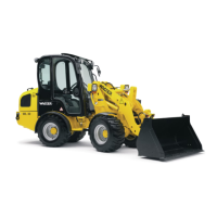
Fuse box 1 (C)
Flash code LED H3 (D) Defective fuse
25F2
37F11
47F3
57F4
6F2.1
7F2.2
88F4
98F5
10 1F9
11 F14