LTN Appendix V—Standard Racked Assembly
wc_tx001216gb.fm 99
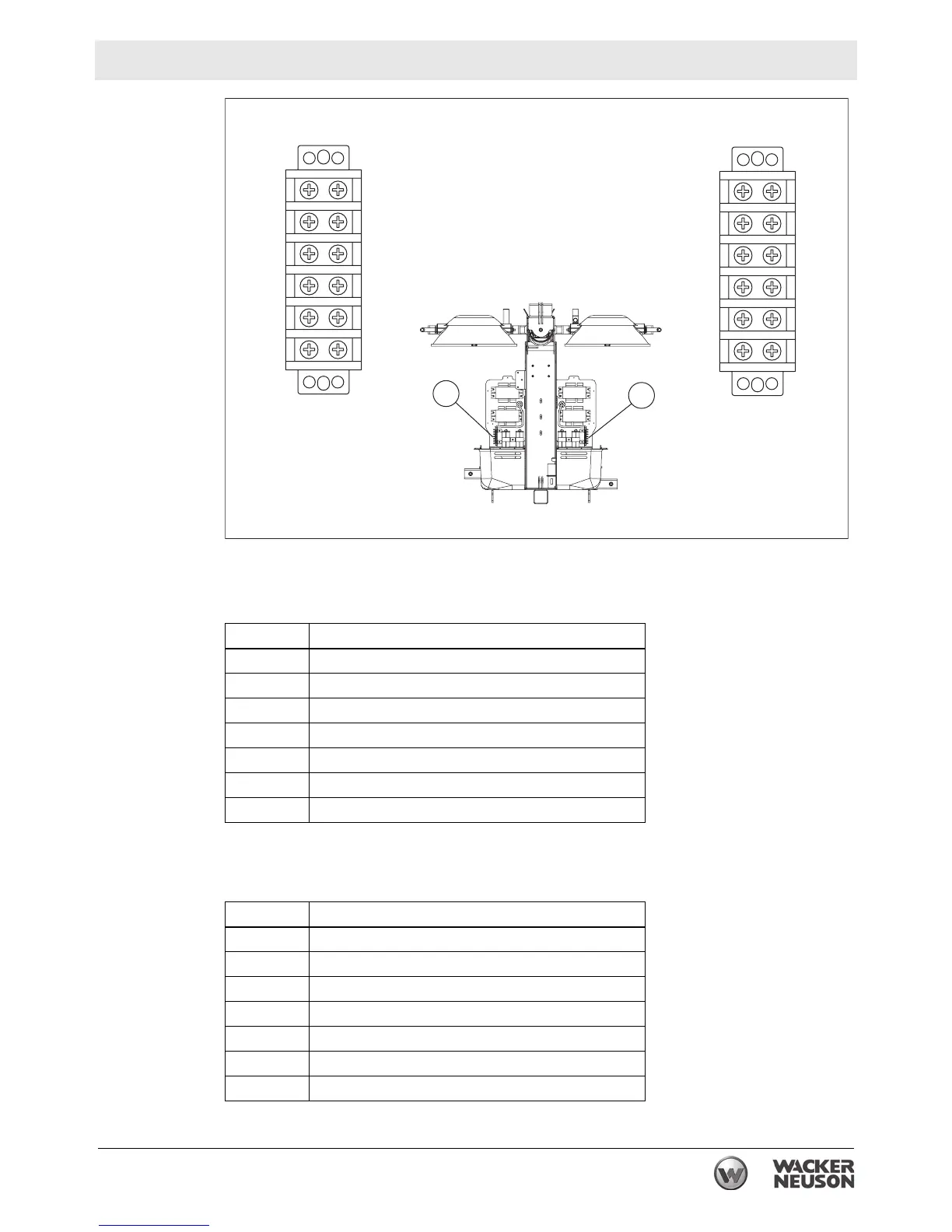
Terminal strip “A” (right side of machine)
Terminal strip “B” (left side of machine)
Position Wire description
A–F Not used
G Black / yellow from ballasts #1 and #2
H Black (#7) from control box
I Yellows (2) from ballast #1
J Yellows (2) from ballast #2
K White (#9) from control box
L Brown and orange from coil cord
Position Wire description
A Black / yellow from ballasts #3 and #4
B Black (#6) from control box
C Yellows (2) from ballast #3
D Yellows (2) from ballast #4
E White (#8) from control box
F White and purple from coil cord
G–L Not used
wc_gr006538
A
B
C
D
E
F
G
H
I
J
K
L
A
B
C
D
E
F
G
H
I
J
K
L
A
“A” “B”
B
 Loading...