Appendix VI—CE Racked Assembly LTN Assembly
wc_tx001217gb.fm 114
14.11 Wiring the Ballasts and Terminal Strips
Procedure
Follow the procedure below to wire the ballasts and terminal strips.
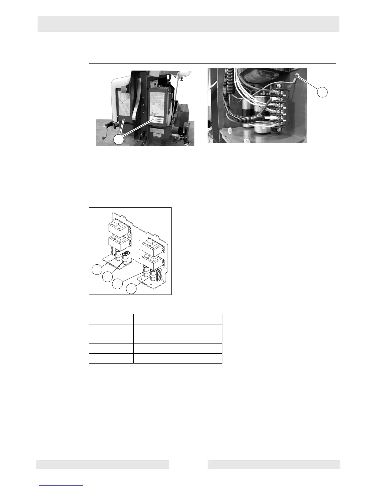
1. Remove the two ballast covers (BC) from the left and right sides of the Light
Tower.
2. Connect the green wire from the coil cord to the hexagonal grounding screw
(G).
3. Locate the four capacitors as shown below.
4. Connect four wires from the coil cord to the capacitors as follows:
5. Connect the remaining wires to terminal strips “A” and “B” according to the
diagram and tables on the next page. Torque all screws to 2.25 Nm (20 in.lbs.).
6. When all wires are connected to terminal strips “A” and “B,” re-install the ballast
covers. Torque the ballast cover mounting screws to 5.0 Nm (3.5 ft.lbs.).
Capacitor Wire from coil cord
1Red
2Black
3 Yellow
4Blue
wc_gr006537
G
BC
1
2
3
4
wc_gr006570
 Loading...