12
wallaceperimetersecurity.comPhone: 866.300.1110
INSTALLATION AND COMMISSIONING CHECKLIST: SETTING GATE LIMITS
Installaon and Commissioning Checklist: Seng Gate Limits
Complete Step Descripon
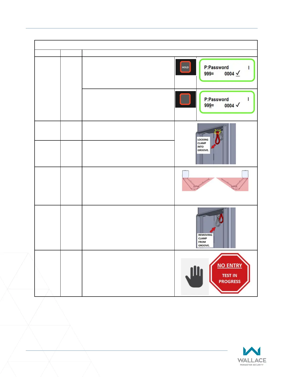
5.3.2-F. Once you’ve reached the master password
use the STOP buon to lock the parameter
in. To do this you must HOLD the stop
buon down unl a check mark appears
by the master password.
Once the parameter value for the master
password is locked in, press the STOP
buon again to return the underscore to
the parameter 999 on the le.
5.3.3 STEP THREE: PROGRAMMING THE
SPEEDGATE
5.3.3-A. Pull manual brake disconnect cable
located inside each column and lock the
cable clamp into the groove provided.
5.3.3-B. Move gate panels to halfway point
between open and closed posions.
PANELS HALF-OPEN: TOP VIEW
5.3.3-C. Release manual brake disconnect (pull
down on the cable and remove it from the
groove) in each column to allow gate to be
moved under power.
5.3.3-D. Clear the gate travel area of all
obstrucons/persons, and place
appropriate warning/signaling devices
to allow for automac gate movement.