SPEEDGATE Installation and Maintenance Manual Revision 1 - MAY 2023
125
TROUBLESHOOTING
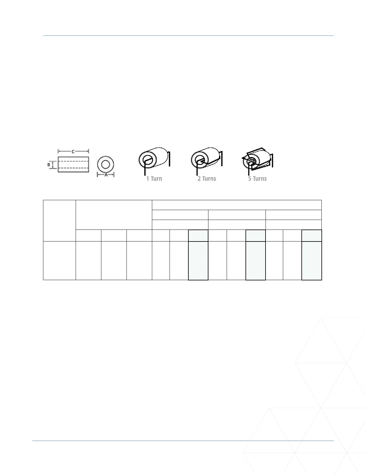
The following ferrite EMI cable core installaon instrucons are provided for informaonal purposes
only. Consult Wallace Perimeter Security for installaon requirements relevant to your project.
1. Unplug cable, located in the operator enclosure, connecng the primary and secondary controller
COM boards.
2. Twist the cable ve mes around the ferrite EMI cable core on both sides (i.e., one cable core at each
end). In some instances, mulple twists may be required; e.g., as many as possible.
3. Plug cable back into board.
PART
NUMBER
DIMENSIONS mm
(inches)
Typical Impedance (Z) in ohms (Ω)
Ω @ 500 KHz Ω @ 1 MHz Ω @ 5 MHz
# of Wire Turns # of Wire Turns # of Wire Turns
A B C 1 2 5 1 2 5 1 2 5
LFB259
128-
000
25.91
(1.020)
12.83
(0.505)
28.58
(1.125)
61 220 1446 106 420 2647 62 240 1487
EMI shielding occurs when the geometry and electromagnec properes of coiled wire over the ferrite
core aenuate high-frequency EMI/RFI electronic noise from acve components, eecvely protecng
other boards or components in the vicinity from EMI contaminaon.