24
wallaceperimetersecurity.comPhone: 866.300.1110
INTRODUCING SPEEDGATE
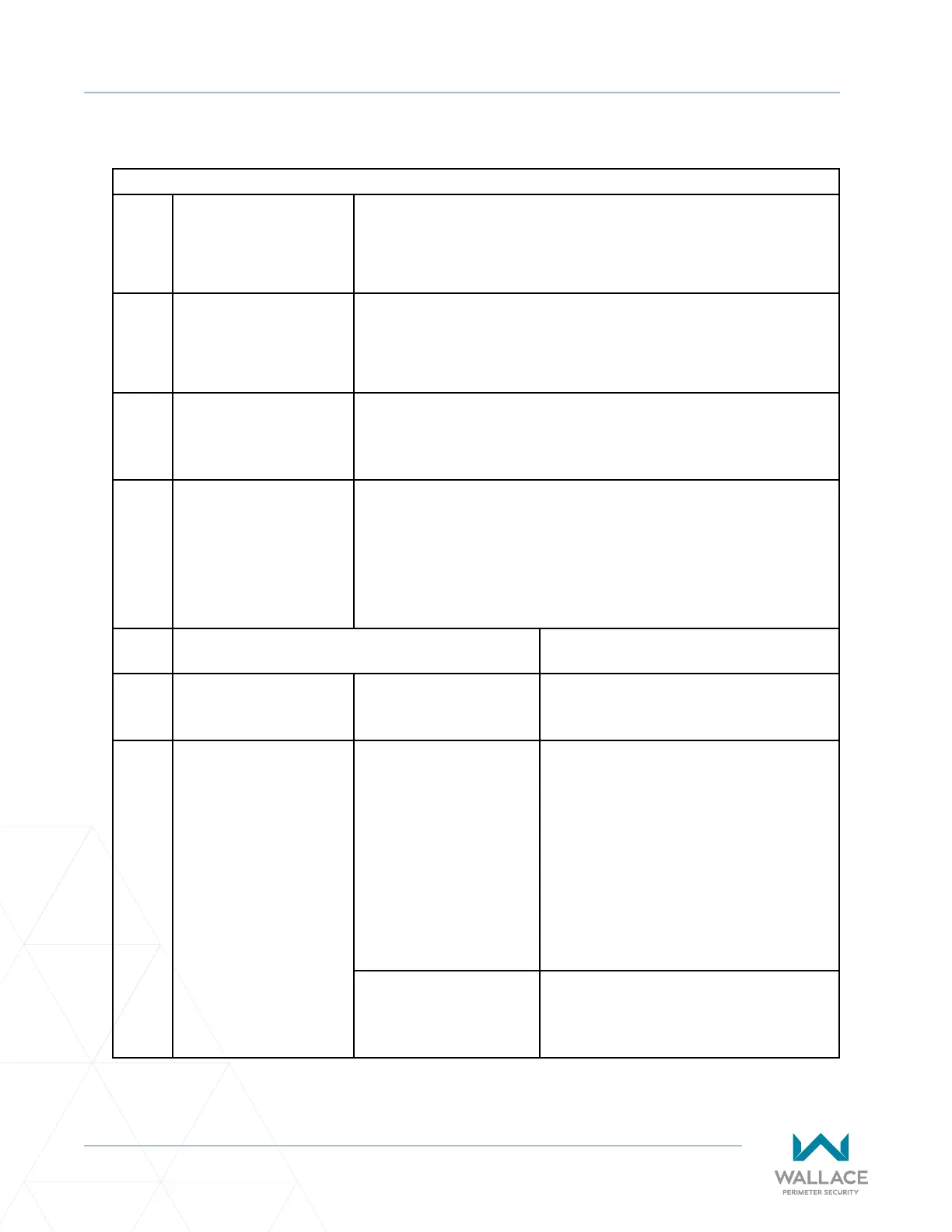
Generally, the SpeedGate consists of ve main components, including three categories of safety devices:
Table 1. SpeedGate Main Components
1� Columns The columns support the guide channel and the panels. The columns
also house all of the drive components for the gate. The columns are
anchored to a concrete foundaon with anchor bolts.
2� Panels The panels (gate leafs) are aached to the columns using hinges. The
minimum opening and closing me for the panels is approximately
8 seconds.
3� Drive Mechanism(s) The panels are driven by means of an electro-mechanical drive
system. The drive mechanism is located in the column. In the
event of a power failure, a manual brake disconnect can be used to
manually open/close the gate.
4� Operator Enclosure The operators can be operated by a push buon staon, vehicle
detector loops, card access system and any device which when
given a command switches a dry contact relay (the relay common is
supplied by the operator). There are also foil keypads on the outside
doors of the operators, each keypad commanding the corresponding
operator and gate.
5. Safety Devices for Obstrucon and Entrapment
Detecon
Refer to Secon
5.1 Inherent Safety Device: Reduced Speed Sensor /
Torque Change Sensor
• “Inherent Entrapment Sensor” on
page 26
5.2 External Safety Devices: Photo Eyes • “External Entrapment Protecon
Sensors” on page 29
• “External Entrapment Sensor Types”
on page 34
• “UL 325 Compliant Sensors” on page
31
• “Photo Eye Installaon” on page
70
• “Photo Eye Alignment” on page 73
• “1. PHOTO EYE - MANDATORY” on
page 87
Audible Horn Device • Info - page 18
• “Open & Close Cycle” on page 26
• “3. AUDIBLE WARNING DEVICE –
MANDATORY” on page 89