SPEEDGATE Installation and Maintenance Manual Revision 1 - MAY 2023
71
PHOTO EYE INSTALLATION
For UL 325 compliance, all external
entrapment protecon sensors
must have N.C. sensor outputs for
monitoring and powering purposes.
Wire Gauge and Type:
18AWG 2C Through-beam Photo Eye Transmier, Shielded
18AWG 4C Through-beam Photo Eye Receiver, Shielded
When unpacking photo eyes, DO NOT DISPOSE OF
THE RECEIVER SUNSHIELDS (“alignment cones”). The
sunshields are eecve at reducing the eects of solar
interference or crosstalk.
Mount photo eye receivers to columns with the shields
intact and adjust as required. If two sets of photo eyes are
being installed on one column and crosstalk is occurring,
remounng photo eyes in the following conguraon
may eliminate this issue:
• Install the transmier above the receiver on one
column.
• Install the receiver above the transmier on the
opposing column.
• Angle the top device upward and boom device
downward to avoid crosstalk.
1. Remove cover from photo eye by removing the 4 corner screws. The cover should not be placed on
photo eye unl the photo eye transmier and receiver are aligned.
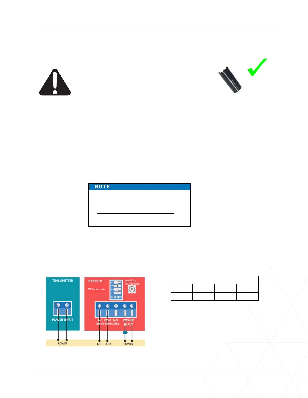
2. Figure 15 shows the wiring and DIP switch sengs of an EMX-MON photo eye (typical through-beam
wiring), the type of photo eye normally shipped with a SpeedGate by Wallace Perimeter Security.
Figure 15. EMX-IRB-MON Photo Eye Wiring
Receiver DIP Switch Sengs
SW1 SW2 SW3 SW4
OFF OFF ON OFF
The operator cycles power to the
transmier while monitoring the
receiver N.C. (Normally Closed) contacts
for proper operaon.