72
wallaceperimetersecurity.comPhone: 866.300.1110
PHOTO EYE INSTALLATION
3. Typical EMX Photo Eye Connecons to Post Terminaon Connecon Board:
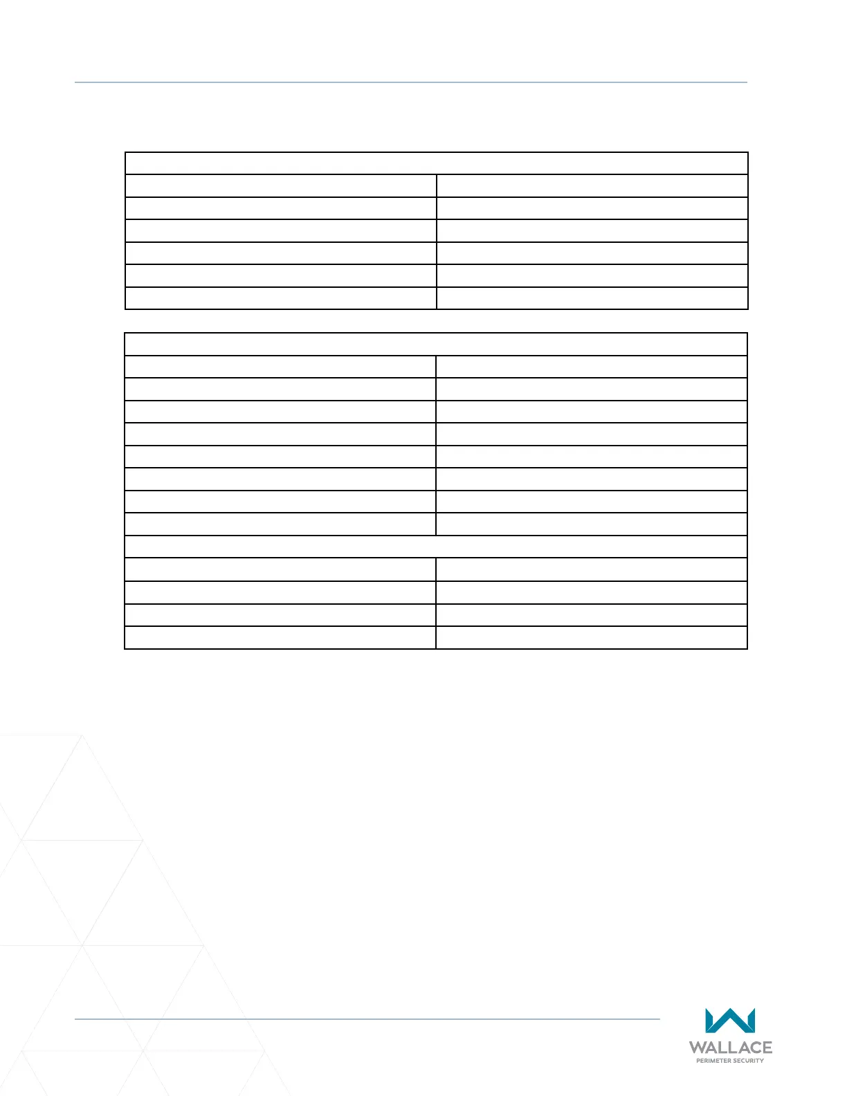
Table 7. Photo Eye Wiring - One Set
Primary Column Boom Receiver: (+)24, top terminal #6
(-)24, top terminal #10
COM, top terminal #4
NC, top terminal #15
Secondary Column Boom Transmier: (+)24, top terminal #2
(-)24, top terminal #9
Table 8. Photo Eye Wiring - Two Sets
Primary Column Top Receiver: (+)24, top terminal #5
(-)24, top terminal #11
COM, top terminal #4
NC, top terminal #7
Primary Column Boom Receiver: (+)24, top terminal #6
(-)24, top terminal #10
COM, boom terminal #7
NC, top terminal #15
Secondary Column Top Transmier: (+)24, top terminal #3
(-)24, top terminal #8
Secondary Column Boom Transmier: (+)24, top terminal #2
(-)24, top terminal #9
Always refer to site-specic drawings issued for the project you are working on for actual electrical
connecons and installaon methods.
Connect post terminaon connecon board to operator cabinet. See schemacs supplied with
controller for connecon details.