76
wallaceperimetersecurity.comPhone: 866.300.1110
GATE OPTIONS
Installaon of Resisve Gate Edges (8.2 kΩ terminang resistor)
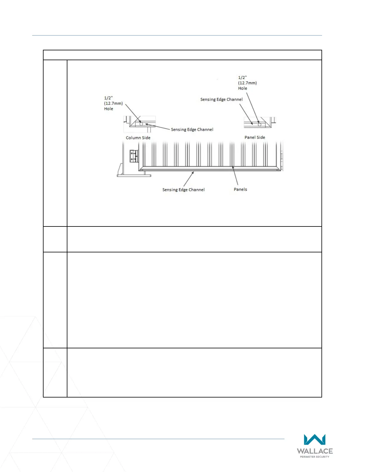
Figure 16. Gate Edge Installaon
3. Lubricate the edge outer lips with soap and water to allow the rubber edge to slide smoothly
into the aluminum channel. When the water dries the edge will no longer slide.
4. There are two cabling formats for resisve edge - a resisve end and a cable end, or both cable
ends. A single resisve safety edge in operaon must have a resisve end and a cable end. For
each gate panel set the horizontal gate edge rubber secon will have a wire pigtail on either
end.
Of the 2 vercals secons one will have a wire pigtail on either end; the remaining gate edge
will have a wire pigtail on one end only. The other end will have the resistor (no wire pigtail).
Once the edge has been slid into the aluminum channel, each end that has a pigtail must be
fed into the ½” (12.7mm) hole that was drilled into the aluminum channel and gate frame. The
gate edges should be connected in SERIES.
5. The installer may choose to provide a door loom kit to hide and protect the cable running
through the gate frame. Follow the manufacturer’s instrucons, ensuring proper hole size for
ngs inseron, placement of collar over ng, clearance checking, posioning of collar on
the sleeve and set screw ghtening.