SPEEDGATE Installation and Maintenance Manual Revision 1 - MAY 2023
77
GATE OPTIONS
Installaon of Resisve Gate Edges (8.2 kΩ terminang resistor)
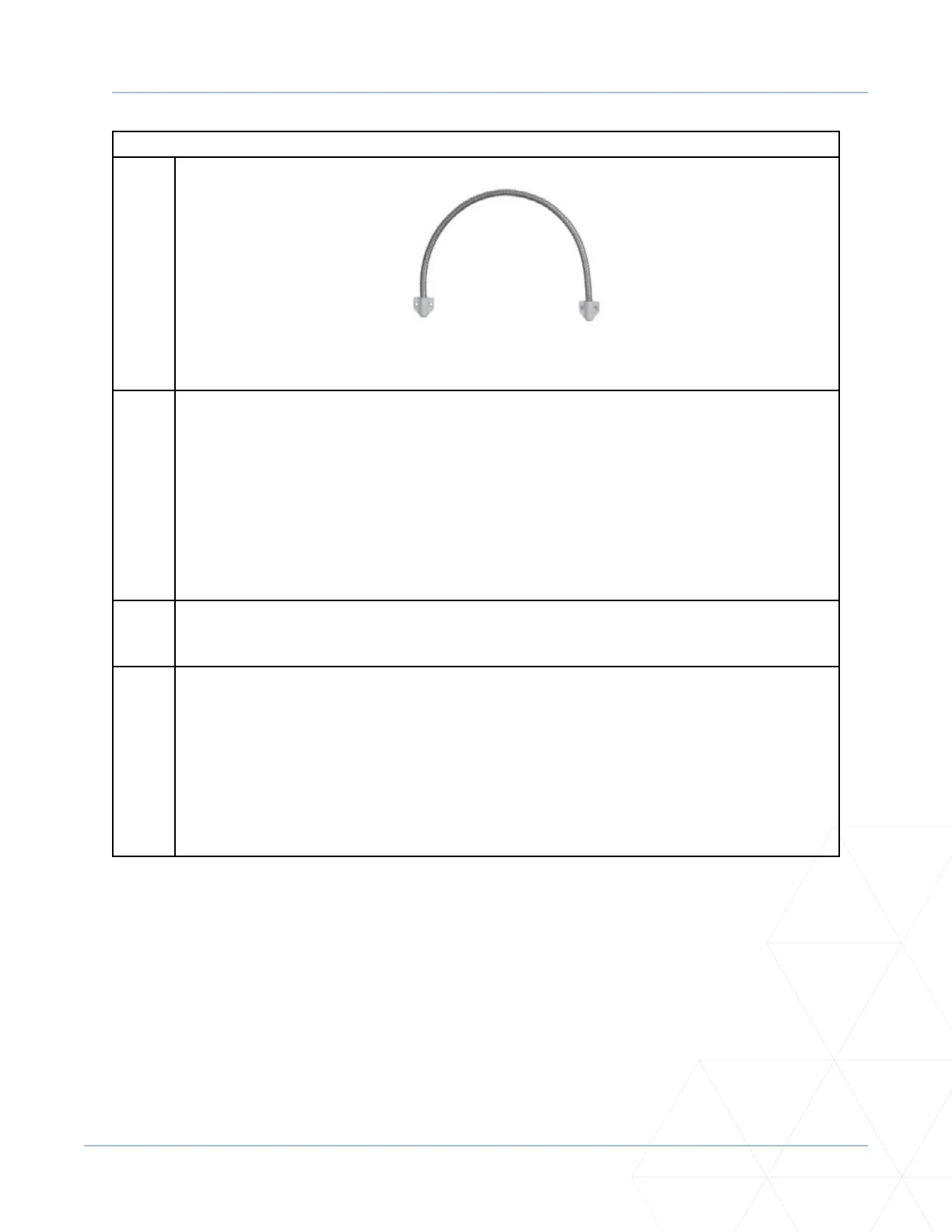
Figure 17. Door Loom
6. Connect gate edge leads from each panel to the post terminaon connecon board located in
the Primary Column. A plug-in communicaon module for the board may also be supplied, if
deemed necessary to achieve a normally closed contact.
Two conductors from each gate panel are terminated on the post terminaon connecon
board.
Blue/Brown wires in heavy black jacketed gate edge lead are terminated on the connecon
board. Make sure gate edge wiring is not pinched/kinked in at panel to column connecon.
7. Connect post terminaon connecon board to operator cabinets using 18-gauge mul-
conductor cable. See schemacs supplied with controller for connecon details.
8. Test the gate edges once they are connected in series for 8.2 kΩ. Readings from 8.0kΩ to 8.5kΩ
are acceptable.
Test the operaon of the reversing edge to be certain that it is funconing. Test by placing a
rigid obstrucon in the path of the gate travel so the edge sensor will make contact.
The gate will stop and reverse upon contact with the obstrucon. Advise the user of the gate
to be certain to retest this vital funcon weekly.