SPEEDGATE Installation and Maintenance Manual Revision 1 - MAY 2023
99
ELECTRICAL CIRCUIT – OPERATOR
7� HEATER
Wallace Perimeter Security recommends a self-regulang heater be installed in colder climates, rated for
the supplied voltage 208-240V. This opon can be specied when the SpeedGate is ordered.
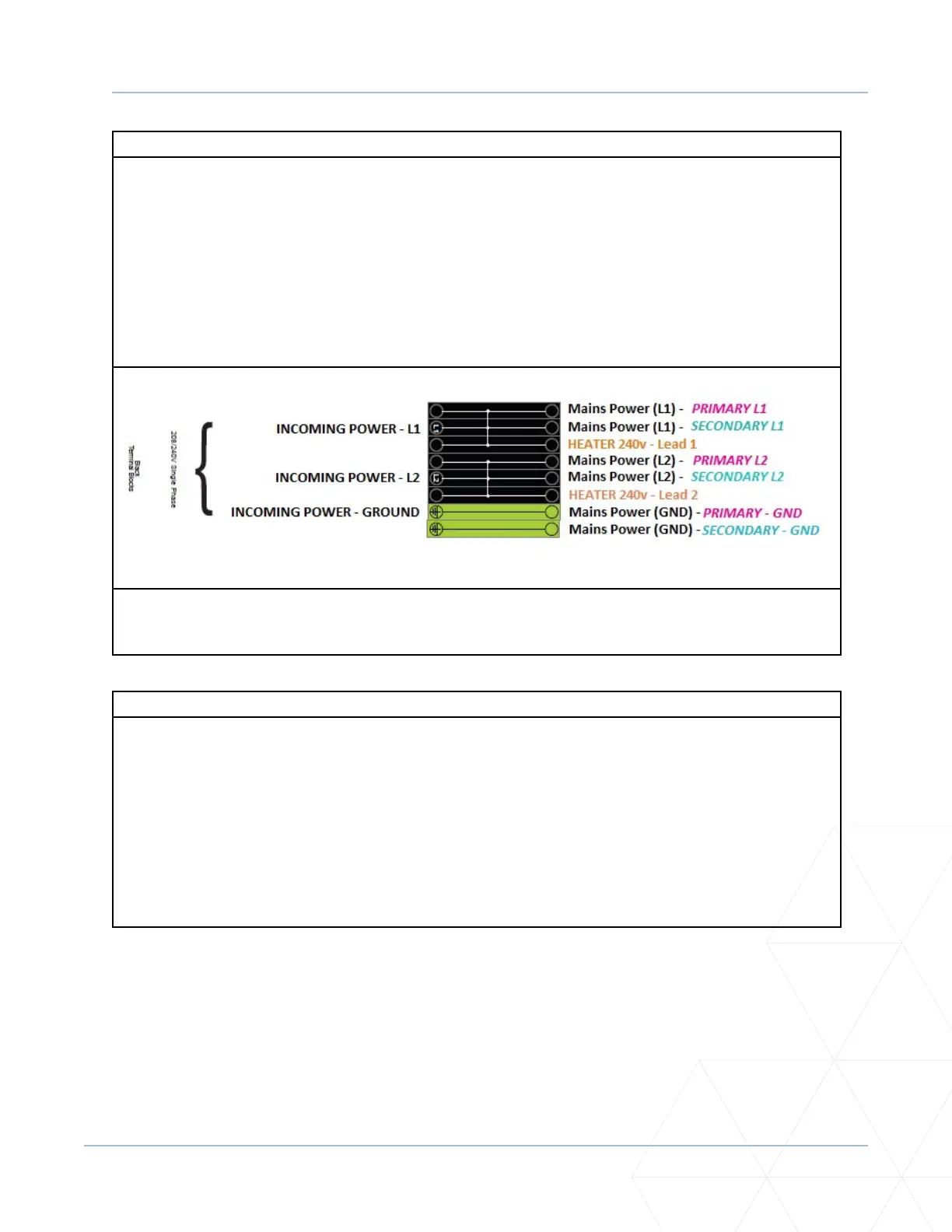
A typical Wallace Perimeter Security shop installaon for a FEIG Gen II (SpeedGate model introduced in
2021) is wired as indicated below. This conguraon allows the heater to remain ON as long as incoming
power is present. FEIG Gen I models (i.e., pre-2021) enable heater operaon only when the operator is
ON.
Connect to terminals L1 & N.
Always refer to site-specic drawings issued for the project you are working on for actual electrical
connecons and installaon methods.
8. VEHICLE LOOPS
The loop leads from the vehicle loops will need to run directly into the Operator Cabinet enclosure
terminal strip.
Loop 1 (Channel 1 Loop):
Channel 1 Loop (which can be congured as an Entrance Loop OR an Exit Loop) typically terminates into
terminal #30 and #31.
Loop 2 (Channel 2 Loop):
Channel 2 Loop (conguraon dependent upon Chanel 1 funcon) typically terminates into terminal #32
and #33.