www.Wayne-Dalton.com
349981 REV2_05/17/2016
©
Copyright 2016 Wayne Dalton, a division of Overhead Door Corporation
10
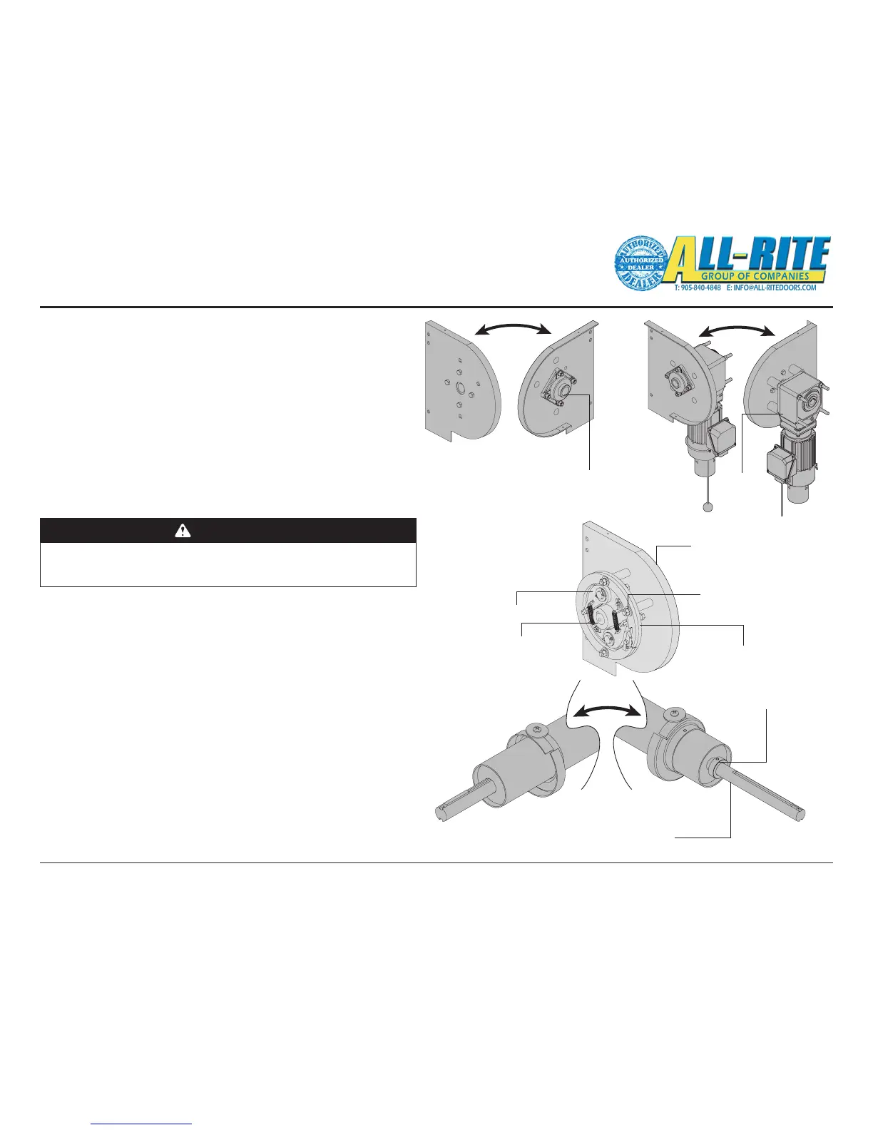
3. IDENTIFY HEADPLATE BRACKETS, Fig. 4–D(a)
Right hand drive is shown (left hand drive opposite).
4. IDENTIFY DRIVE END OF BARREL ASSEMBLY, Fig. 4–E
Right hand drive is shown (left hand drive opposite). The drive end of
barrel assembly typically is longer and has a smaller shaft diameter
than the non-drive end.
5. MOUNT MOTOR/GEARMOTOR TO DRIVE END HEADPLATE
Attach gearmotor to drive end headplate. Drive end headplate may
come with gearmotor and motor already attached.
Installation (continued)
6. LOCATE SET COLLARS, SPACER COLLARS, KEYS, AND DROP STOP
DEVICE (DSD), Fig. 4-D(b) AND 4–E
in hardware box(s). Conrm drop stop device (DSD) matches the
barrel’s downward rotational direction.
A. Slide set collar, small ID (with set screw) onto drive end shaft of the
barrel assembly, Fig. 4–E. DO NOT tighten set screw at this time.
B. Slide spacer collar onto the drive end shaft of the barrel assembly.
The spacer collar separates the set collar from the headplate
bearing and has no set screws.
C. Slide set collar, 1-1/2” ID with set screw, onto non-drive end shaft of
the barrel assembly. DO NOT tighten set screw at this time.
D. Slide spacer collar onto the non-drive end shaft of the barrel
assembly. The spacer collar separates the set collar from the
headplate bearing and has no set screws.
WARNING
Perform the following installation steps 6A through 6D carefully. The
Drop Stop Device MUST BE INSTALLED to protect against rapid closure of
the door which could result in death or serious injury.
Fig 4–D(a)
Non-Drive End Headplate
Drive End Headplate
Gear
motor
Bearing
Bracket Bearing
Fig 4–D(b)
Non-Drive End
Headplate
DSD Rotor
DSD Stator
1/2” - 13 Carriage
Bolt, Lock Washer, Nut
DSD Hub
Fig 4–E
Set Collar, 1-1/4" or 1-1/2" ID,
(with 2 set screws)
Non-Drive End Drive End
Notice smaller shaft (1-1/4” or
1-1/2” ID) diameter on drive end