www.Wayne-Dalton.com
349981 REV2_05/17/2016
©
Copyright 2016 Wayne Dalton, a division of Overhead Door Corporation
19
Installation (continued)
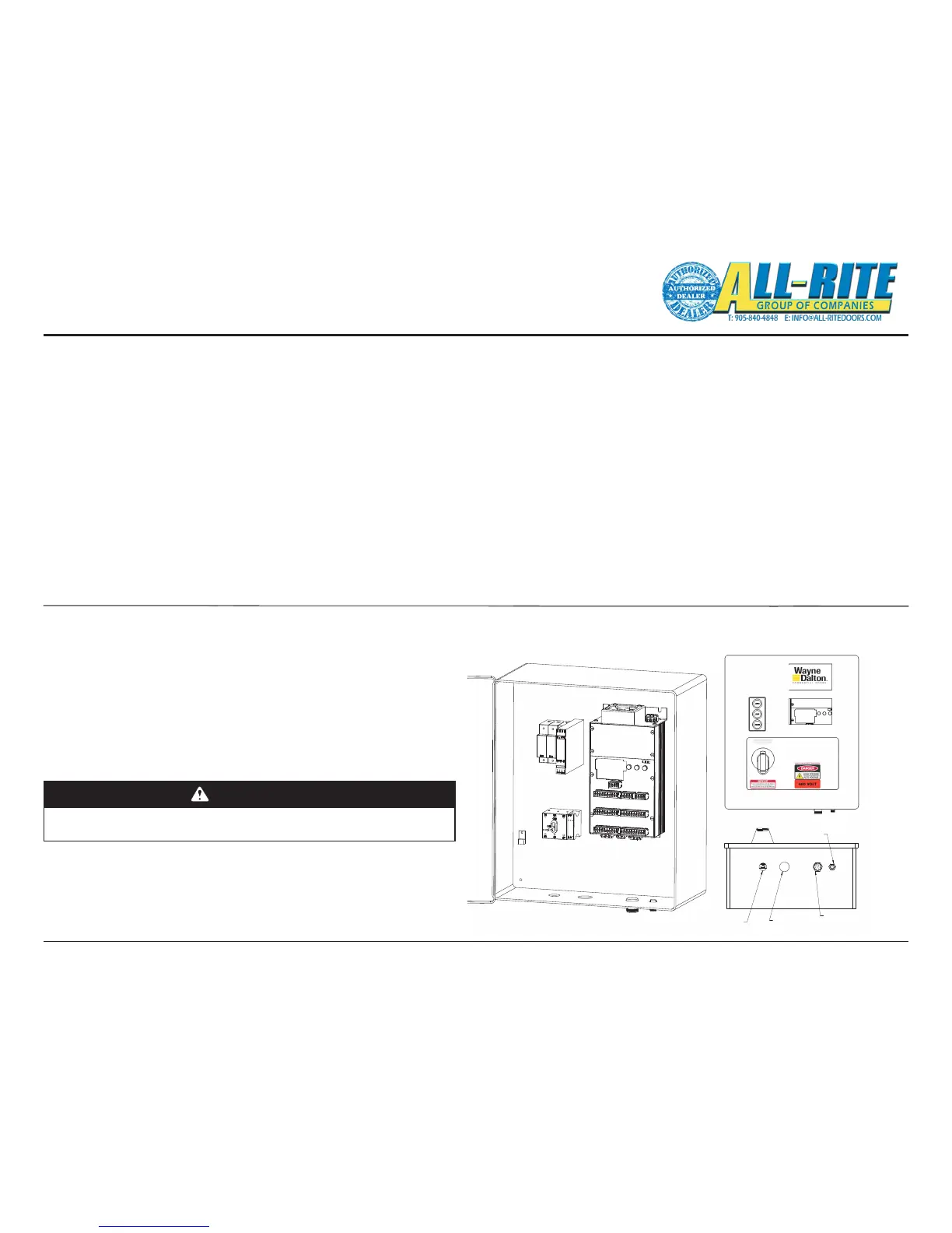
15. LOW VOLTAGE WIRING
A. Connections to the door are completed by attaching the two
screw-in cables to the control panel’s base, Fig. 5–I page 27.
1. 5 pin cable connector
• Position Sensor
2. 12 pin cable connector
• Photoeye Reciever
• Photoeye Transmitter
• Sensing Edge
• Hand Crank Interlock Switch
• Optional Input 1
• Optional Input 2
3. Two options may be connected to the Junction Box by
the installer. Additional options must be wired to the
spare inputs on the Control panel. Use the corresponding
option inputs.
• Radio Remote to the Junction Box connector 6 labeled
“Option 2”.
• Floor loop to the Junction Box connector 5 labeled “Option 1”.
• Motion Detector to the Junction Box connector 5 labeled “Option 1”.
• Wall mounted push button stations to the main Control Panel
Fig. 8–J on page 51.
Fig 4–U
Note: When installing push buttons, use the 24V supplied by the
Control Unit as the common.
SENSOR CABLE
BOX CABLE
MOTOR CABLE
12 PIN JUNCTION
5-PIN POSITION
MAIN POWER
(FROM DISCONNECT)
Fig 4–U
16. MOTOR & POWER WIRING (HIGH VOLTAGE) (These tasks are also diagrammed in Fig. 5–D, 5–G & 5–H on pages 24-26.)
A. Route Motor Power Cable (provided, factory wired to motor) through water-tight tting in the SECOND hole from left side of Control Panel bottom.
1. Connect the lighter gauge, twisted pair wires to the blue colored Motor Brake terminals next to the disconnect switch. Either wire can connect to
either terminal. It is labeled “B1” and “B2”.
2. Connect the green and yellow ground wire, the braided
cable shield and the non-insulated ground wire together to
the Green and Yellow terminal.
3. Connect the thicker motor wires to Terminals T1, T2 and T3 on
the green screw connectors on the bottom left of the
control unit. The order doesn’t matter since the motor
rotation can be changed using the internal programming
during Set-up in Section 6.
WARNING
Before beginning this phase of installation, ensure POWER
SUPPLY is disconnected!
A licensed electrician must perform the following step.
B. Route Main Power Cable (not provided) through a
water-tight tting (not provided) in the FIRST hole from the
left side of the Control Panel bottom.
• Connect 3-phase power lines to the disconnect. Connect
the ground wire to the Ground Terminal to the left of the disconnect.
1-800-827-3667 (DOOR)