www.Wayne-Dalton.com
349981 REV2_05/17/2016
©
Copyright 2016 Wayne Dalton, a division of Overhead Door Corporation
32
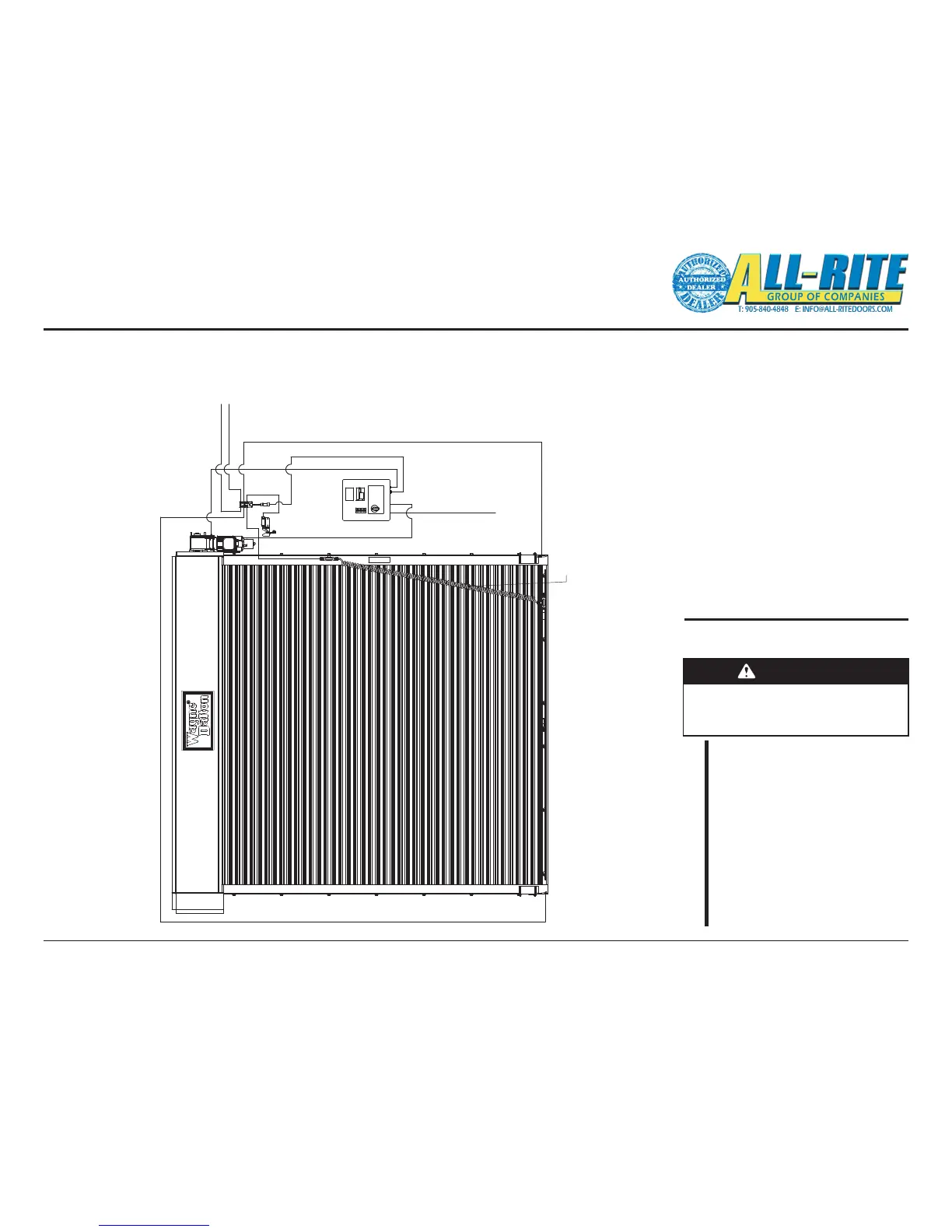
REFERENCE: CONVENTIONAL WIRE ROUTING
NOTE: Components/component locations are shown here for reference only. Some parts not shown for clarity.
Your unit installation and wire routing may be dierent.
Installed wire routing for example only.
Fig 5–P
After completing the instructions
contained in this section, check:
Wiring Check List
WARNING
Making the checks outlined below
will help to ensure that the unit is
wired properly.
CHECK
– Double check all connections
are tight.
– Check all cables are secured
(not hanging loose where
they might become
interference).
– Ensure there are no loose
tools or materials inside the
Control Panel or Junction
Box.
Wiring (continued)
OPTION 1
OPTION 2
MAIN POWER
JCT BOX TO PHOTOEYE RECEIVER
CTRL PANEL TO MOTOR
JCT BOX TO SENSING EDGE JCT BOX,
THEN TO SENSING EDGE
CTRL PANEL TO PS
JCT BOX TO CTRL PANEL
JCT BOX TO PHOTOEYE TRANSMITTER
JCT BOX TO PHOTOEYE TRANSMITTER