www.Wayne-Dalton.com
349981 REV2_05/17/2016
©
Copyright 2016 Wayne Dalton, a division of Overhead Door Corporation
16
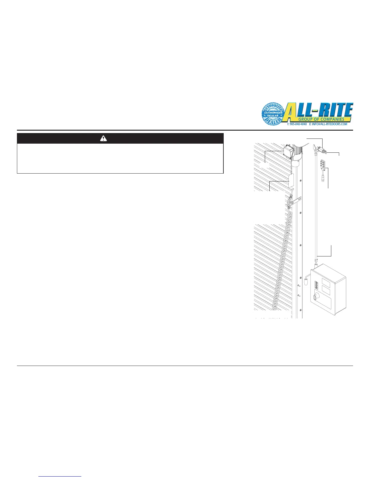
Brake Release
Cord
NOTE: Bottom of
Brake Release
Cord Minimum of
8’ from floor
Hand Crank
Interlock Switch
Crank Handle
Retainer
Hand Crank
Motor
Junction
Box
14. MOUNTING AND CONNECTING/WIRING STANDARD ELECTRICAL COMPONENTS
This step encompasses the installation and wiring of several components;
• Crank Handle Support Bracket and Switch,
• Junction Box,
• Control Panel,
• Photoeye, and
• Sensing Edge.
A. Install Crank Support Bracket and Interlock Switch. The top end of the hand crank will
mount onto the Crank Support Bracket and be held vertically in place to the wall using the
provided clips and fasteners.
NOTE: Ensure the nished position of the Hand Crank hangs vertically above the oor and
where the crank handle will not interfere with anything.
1. Find a suitable location for mounting the Crank Support Bracket, Interlock Switch, and
Hand Crank components that are near the motor and does NOT interfere with the
operation or installation of other components, Fig. 4–R.
2. Using appropriate fasteners and pre-drilled holes, mount the Crank Support Bracket
to the wall.
3. Using appropriate fasteners, mount the Interlock Switch to the Crank Support Bracket.
4. Place the hook end of the Hand Crank onto the Support Bracket and verify hook
rests on top of and engages the Interlock Switch actuator. Make adjustments as
required.
NOTE: Proper engagement of the Interlock Switch actuator is important!
5. Route the Interlock Switch cable from the switch to the future location of the Junction
Box.
6. Hang the Hand Crank on the Support Bracket.
DANGER
LINE POWER should NOT be installed at this time. In the following steps electrical
components will be physically mounted. Ensure that all incoming power supplies have
been de-energized prior to beginning work on attachment of electrical control systems. Use
proper Lock Out/Tag Out procedures.
Do NOT connect components to electrical supply until directed to do so.
Fig 4–R
Installation
(continued)