www.Wayne-Dalton.com
349981 REV2_05/17/2016
©
Copyright 2016 Wayne Dalton, a division of Overhead Door Corporation
31
RADIO RECEIVER
JUNCTION
BOX
WHITE
BLACK
24VDCSIGNAL 0V
RED
FIG 5-OC
8
JUMPER
3
5
LOOP
7
1112
SIGNAL (24V) WHITE
0V BLACK
24V RED
910
6
DETECTOR
4
LOOP WIRE
JUNCTION
BOX
FIG 5-OE
1
2
3
4
5
6
7
8
WHITE BOX
INDICATES SETTING
WHITE (COM)
YELLOW (NO)
BLACK
DETECTOR
RED
BROWN (0V)
WHITE
GREEN (24VDC)
MOTION
GREY (NC)
JUNCTION
BOX
FIG 5-OD
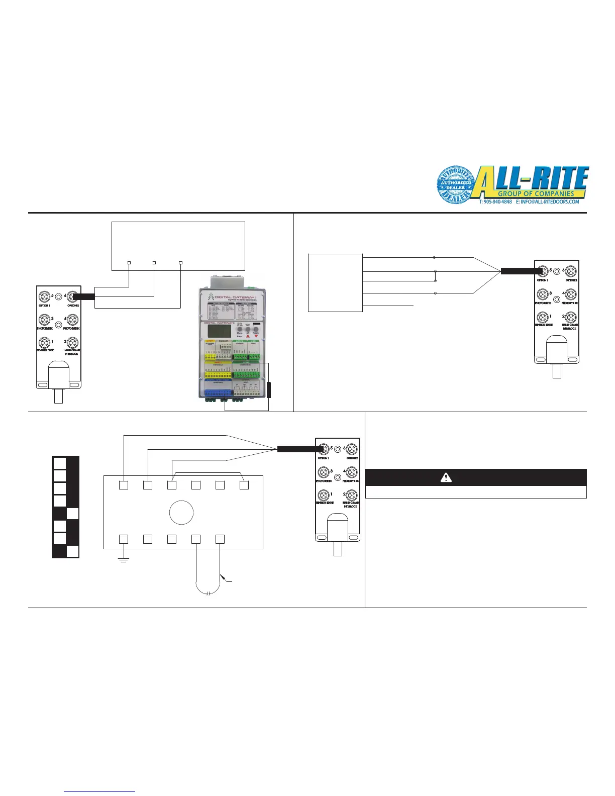
Wiring (continued)
5. Options wiring and settings
-Wire the supplied cables to the following options as shown in
FIG 5-OC, FIG 5-OD, FIG 5-OE.
A. For the radio receiver, wire the supplied receiver load into
the control unit from MAN1 to 24VDC (blue terminal).
CAUTION
Door will open/close once connected.
1. Access the menu and navigate to system cong->
Inputs-> Man1-> Logic.
2. Select NC parameter and exit the menu.
B. The motion detector and loop detector can be operational
once wired to the junction box. They are wired for the default
conguration.
1. To update the auto close timer, access the express
menu->Auto1 Timer.
RECEIVER
LOAD
CONTROL UNIT
(SEE ALSO FIG 8-H)
LOOP DETECTOR
DEFAULT SETTINGS