www.Wayne-Dalton.com
349981 REV2_05/17/2016
©
Copyright 2016 Wayne Dalton, a division of Overhead Door Corporation
11
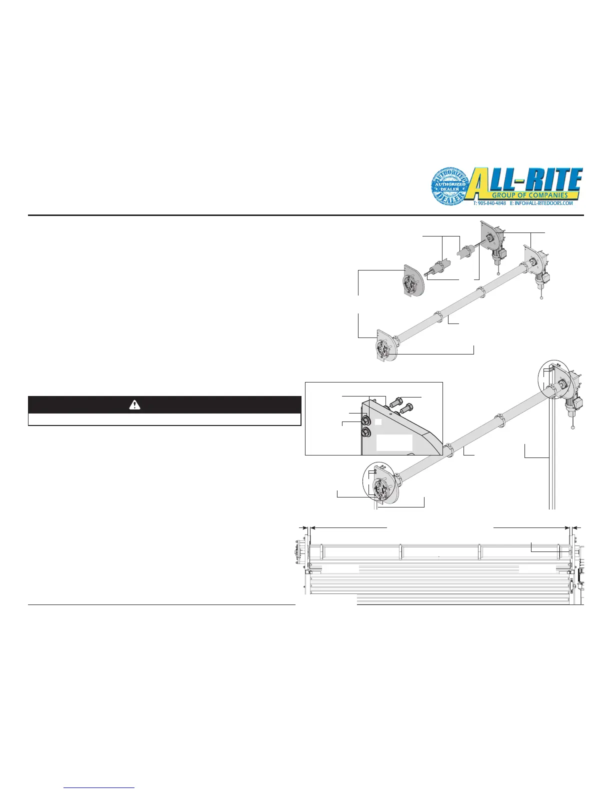
8. MOUNT BRACKETS AND BARREL ASSEMBLY, Fig. 4–F
A. Headplate brackets must be square to the wall and parallel.
B. Use hex bolts, nuts and washers (provided) to fasten headplate
brackets to the outside of the wall angles. Use washers under both
the bolt head and nut.
C. Bolt heads must be on the inside of the headplate brackets.
D. Use a level to make sure the barrel is level.
NOTE: A level barrel is crucial to the correct operation of the curtain. If the
barrel is NOT level, the curtain will begin to "telescope" towards the low
end and may damage the curtain.
E. Position the barrel assembly such that the curtain, mounted on the
barrel, will be centered between the headplates, Fig. 4–H.
F. Tighten bracket bearing set screws on both headplates to prevent
barrel from sliding side to side.
G. Slide inner set collars and spacer collars against headplate bearings
and tighten set screw on the set collars. (Spacer collar does not
have set screw.)
I. Tighten Drop Stop Device hub set screws.
Installation (continued)
7. ASSEMBLE BARREL AND HEADPLATE BRACKETS, Fig. 4–G
Apply lubricant (anti-seize compound (provided)) to inside of gearmotor
bearing.
A. Slide the drive headplate bracket bearing and gearmotor/drive bracket
onto drive end of the barrel shaft (long end).
B. Align keyways and insert supplied key. If possible leave key ush with
the shaft end. (It can be used to align drive sprocket.) Do not trim yet.
C. Slide the non-drive headplate bracket and bearing onto the non-drive
end of the barrel shaft (short length/large diameter).
D. The Stator assembly is bolted to the bracket assembly with (3) 1/2”
screws with hex nuts at the factory.
E. Align DSD (Drop Stop Device) rotor keyway with non-drive shaft end
and insert 3/8” X 3/8” X 3” key into slot on non-drive end shaft
F. Lightly tighten the set screws on the hub of the DSD rotor.
G. The distance between the outside of the headplate brackets
should be less than the "S" dimension, Fig. 3–C.
H. Do NOT tighten bearing or set collars set screws at this time.
NOTE: Do NOT install Position Sensor assembly and roller chain at this time.
CAUTION
Use proper lifting equipment and correct lifting procedures to avoid injury.