www.Wayne-Dalton.com
349981 REV2_05/17/2016
©
Copyright 2016 Wayne Dalton, a division of Overhead Door Corporation
14
Installation (continued)
If you have welded "E" assemblies or "Z" assemblies factory assembled and
have already installed them in a previous step, skip Step 10.
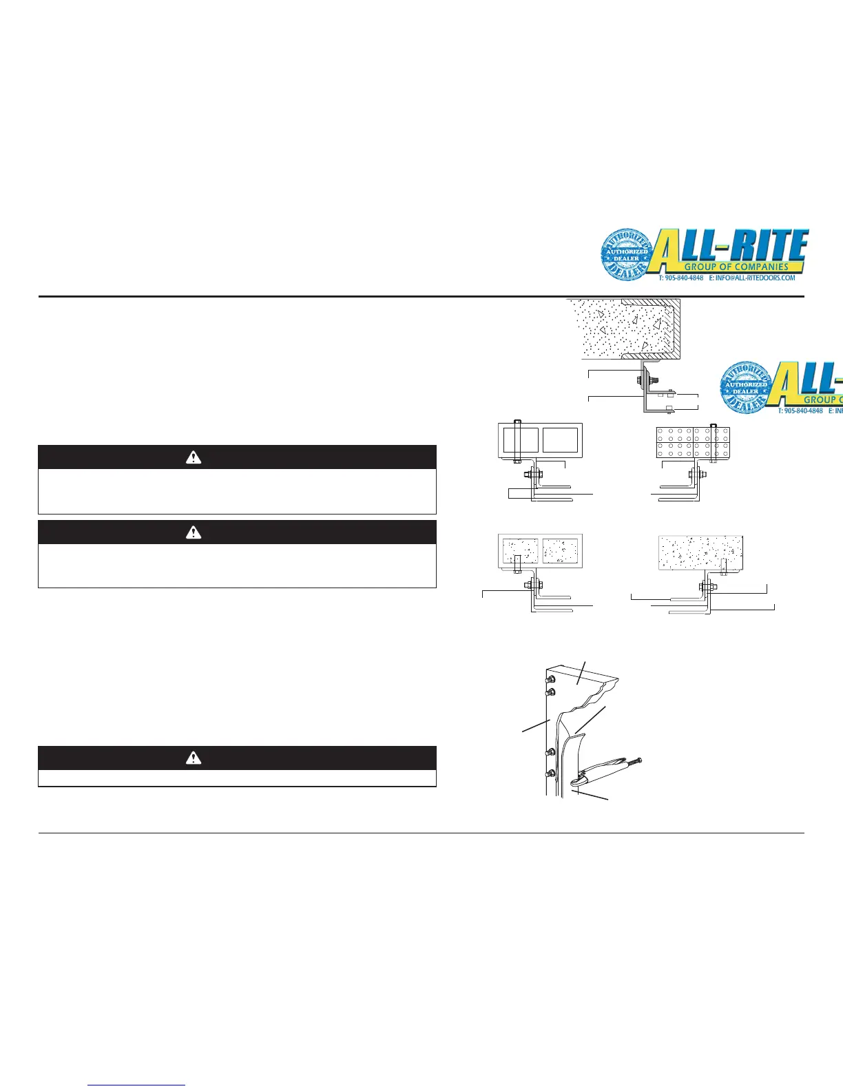
11. INSTALL GUIDE ANGLES
Bolt the middle angles and outer angles to the wall angles as shown
in Fig. 4–L. (Wall angles may be mounted inside or outside based on
installation requirements, Fig. 4–M.)
• The "Guide Gap" MUST be set to the value given on the Installation
Data Sheet. Refer also to Door Specications on page 7.
Fig 4–N
WARNING
Improper use of Hand Crank can cause severe injury or death. Review and
UNDERSTAND the operation of the Hand Crank, (see page 12), prior to
performing the following installation steps.
12. OVERTRAVEL PREPARATION
A. Place locking pliers or other secure clamping tool on both guides at
2 to 3 inches below the channels on the guide angles as shown in
Fig. 4–N. (The guides are made up of the middle and outer angles.
The pair are referred to as the "Guide Angles".)
B. Create slack in the slings/ropes, then (using the hand crank) slowly
lower the curtain and bottom bar in between the Guide Angles and
let the bottom bar rest on the locking pliers.
WARNING
In the following step, ensure clamping tools are securely fastened to the guide
angles; if clamping tools or locking pliers are NOT secure the curtain may fall
to the oor.
WARNING
Ensure the slings/ropes are securely fastened after adjusting! Refer to Fig. 4-J
Fig 4–L
Wall Angle
Door Opening
Outer Guide Angle
Guide Gap
Fig 4–M
“Z” Guide
Outside Angle
“Z” Guide
Middle Angle
Wall
Angle
“C” Dimension
Guide Gap
Wall Angle
Wall Angle
Wall Angle
“C” Dimension