www.Wayne-Dalton.com
349981 REV2_05/17/2016
©
Copyright 2016 Wayne Dalton, a division of Overhead Door Corporation
29
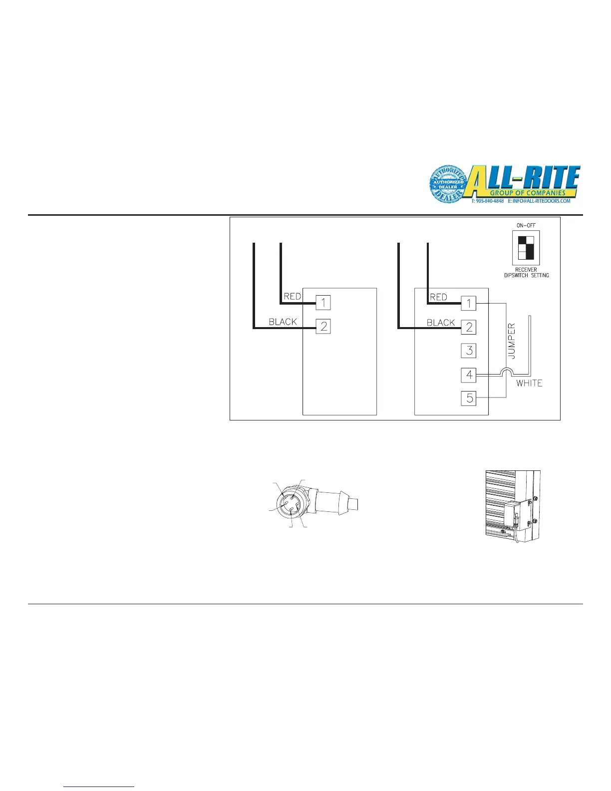
Wiring
2. Photoeye ADJUSTMENT
Photoeye wiring connections were completed in
a previous step (Mounting Electrical components
on page 17).
• Final adjustment of the Photoeyes will be
made after power is supplied to the door
system.
– Verify the Photoeye transmitter LED is on,
indicates power is on.
- Loosen the mounting screws on both
Photoeyes and adjust position until the
LED on the reciever is steadily on.
– Lock the mounting screws down, being
sure not to move the Photoeyes out of
alignment.
PHOTOEYE
TRANSMITTER
PHOTOEYE
RECEIVER
* Photoeye cables are wired at the
factory with a M12 connector.
wire colors are for reference.
NO FIELD WIRING REQUIRED.
(GND)(GND) 24V 24V
SIGNAL
WHITE BOX INDICATES
SETTING
TIMER TURNED
CCW ALL THE WAY
Fig 5–K
Fig 5–L
Fig 5–M
PHOTOEYE
Photoeyes are attached
to their protective shields
at the factory and must
be mounted to the guides
using the hardware provided.
For parking garage applications
Photoeyes may be mounted higher
to prevent the beam from shooting
beneth vehicles.
Photoeyes are attached
to their protective shields
at the factory and must
be mounted to the guides
using the hardware provided.
2. N/C
KEY
1. POWER (RED)
4.SIGNAL ( WHITE)3.GND ( BLACK)
Photoeye Reciever Cable connects to Junction Box