CFW500 | 7
General Information
English
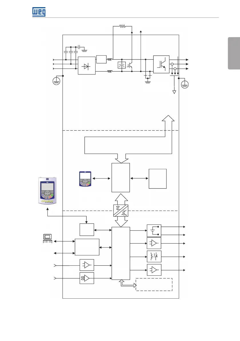
Analog input
(AI1)
(*)
Digital inputs
(DI1 to DI4)
(*)
Supplies for electronics and interfaces between
power and control
RS485
Power
Brake resistor (optional)
Motor
U/T1
V/T2
W/T3
Inverter
with IGBT
transistors
Power
supply
R/L1/L
S/L2/N
T/L3
Capacitor bank DC Link
Braking IGBT (available in the
inverters CFW500...DB...)
HMI
CPU
32 bits
"RISC"
EEPROM
(memory)
User’s
plug-in
card
Interfaces
(RS232,
RS485
or USB)
Analog output (AO1)
(*)
Power supply 24 V
Power supply 10 V
Digital output DO1 (RL1)
Digital output DO2 (TR)
(*)
HMI (remote)
Feedback:
- voltage
- current
PE
PE
Memory card (MCard)
Accessory
Control
Control
Standard plug-in
= Human-machine interface
Preload
Three-phase
rectifier
MODBUS
Software WLP
SUPERDRIVE
(*)
PC
= connection for DC link
= connection for brake resistor
+UD BR -UD
DC Link chokes
RFI filter
(*) The number of analog/digital inputs/outputs, as well as other resources, may vary according to the plug-in module used. For further information,
refer to the guide supplied with the accessory.
Figure 2.3: Block diagram of CFW500 for frame size F