14 | CFW500
Installation and Connection
English
Allow the minimum clearances indicated in Figure B.3 on page 172, in order to allow the cooling
air circulation. Do not install heat sensitive components right above the inverter.
ATTENTION!
When installing two or more inverters vertically, respect the minimum
clearance A + B (as per Figure B.3 on page 172) and provide an air deflecting
plate so that the heat rising up from the bottom inverter does not affect the
top inverter.
Provide independent conduits for the physical separation of signal, control,
and power cables (refer to the Section 3.2 ELECTRICAL INSTALLATION on
page 15).
3.1.2.1 Cabinet Mounting
For inverters installed inside cabinets or metallic boxes, provide proper exhaustion, so that the
temperature remains within the allowed range. Refer to the dissipated powers in Table B.4 on
page 162 and Table B.5 on page 164.
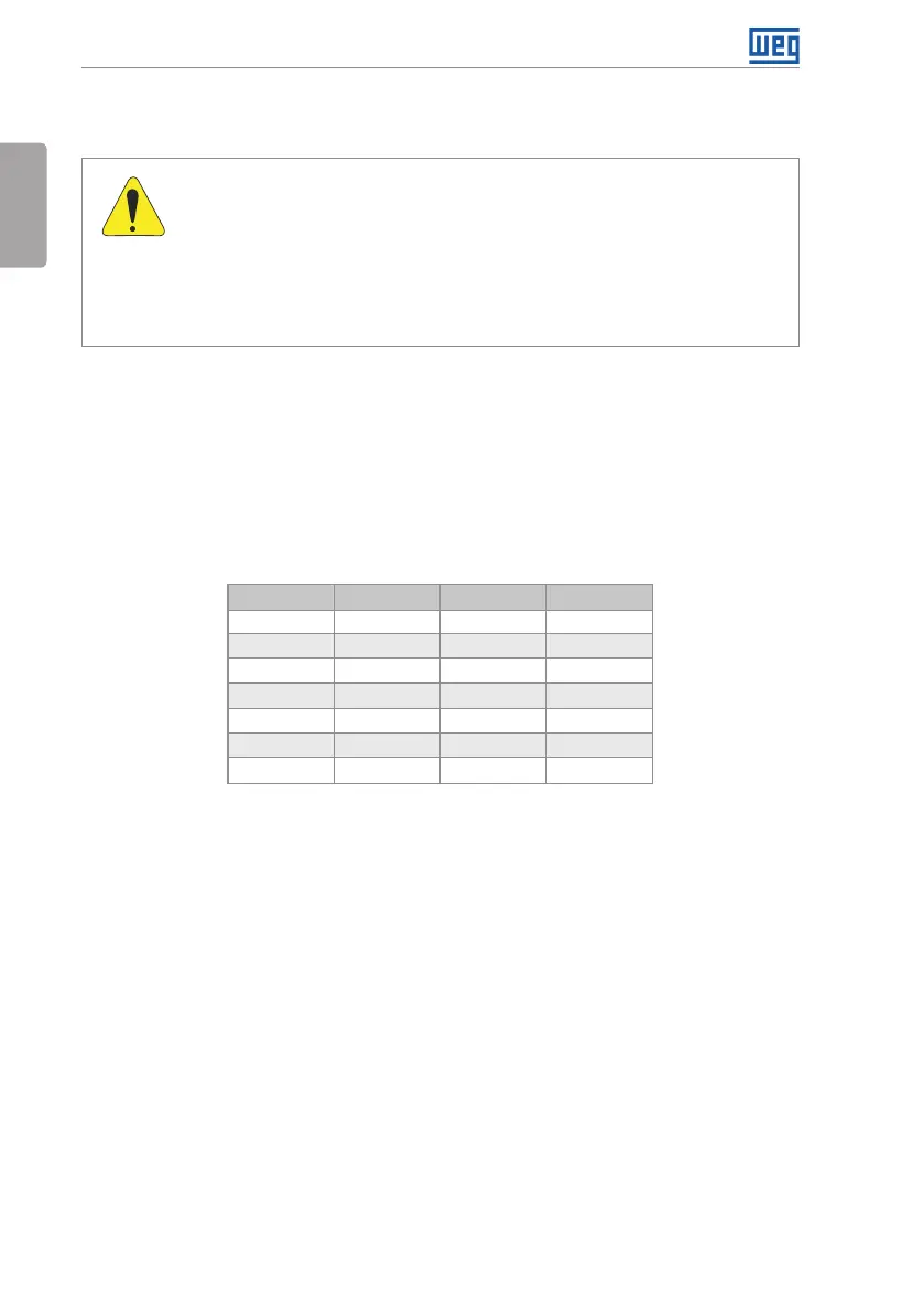
As a reference, Table 3.1 on page 14 shows the air flow of nominal ventilation for each frame size.
Cooling Method: fan with air flow upwards.
Table 3.1: Air flow of the fan
Frame Size CFM I/s m
3
/min
A 20 9.4 0.56
B 30 14.1 0.85
C 30 14.1 0.85
D (T2)
(*)
100 47.2 2.83
D (T4)
(**)
80 37.8 2.27
E 180 84.5 5.09
F 214 100.4 6.05
(*) T2 - CFW500 frame size D line 200 V (200...240 V).
(**) T4 - CFW500 frame size D line 400 V (380...480 V).
3.1.2.2 Surface Mounting
Figure B.3 on page 172 illustrates the procedure for the installation of the CFW500 on the
mounting surface.
3.1.2.3 DIN-Rail Mounting
In frame sizes A, B and C, the inverter CFW500 can also be mounted directly on 35-mm rail as
per DIN EN 50.022. For this mounting, you must first position the lock
(*)
down and then place
the inverter on the rail, position the lock
(*)
up, fixing the inverter.
(*) The fastening lock of the inverter on the rail is indicated with a screwdriver in Figure B.3 on page 172.
3.1.2.4 Flange mounting
In frame size F, the inverter CFW500 can also be mounted in flange. For this mounting, remove
the drive mounting brackets for flange mounting. The protection degree of the inverter outside the
panel is IP55 for flange mounting. It is necessary to provide proper seal for the opening where the
inverter is installed to ensure the protection degree of the panel. Example: sealing with silicone.
Please refer to Figure B.3 on page 172 for flange mounting data.