CFW500 | 23
Installation and Connection
English
3.2.5 Control Connections
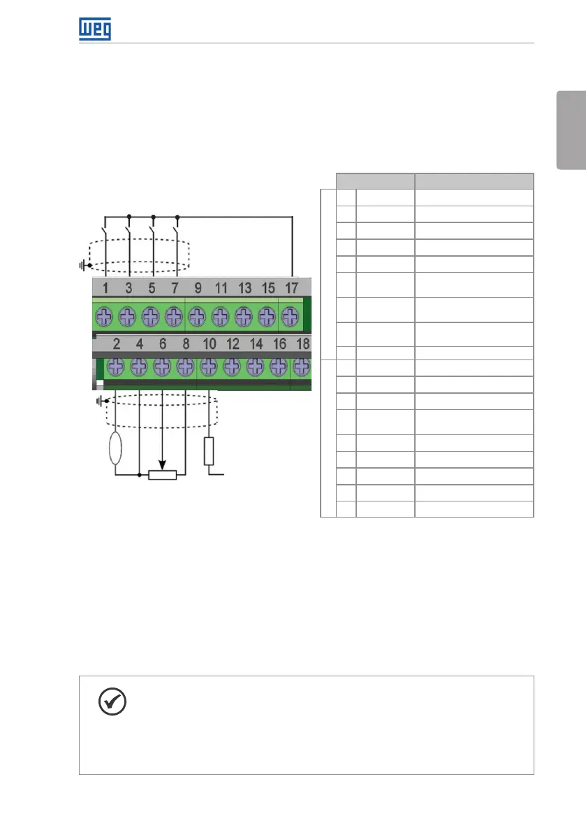
The control connections (analog input/output, digital input/output and interface RS485) must
be performed according to the specification of the connector of the plug-in module connected
to the CFW500. Refer to the guide of the plug-in module in the package of the product. The
typical functions and connections for the CFW500-IOS standard plug-in module are shown in
Figure 3.4 on page 23. For further details about the specifications of the connector signals,
refer to Chapter 8 TECHNICAL SPECIFICATIONS on page 44.
DI1
DI2
DI3
DI4
+24 V
D O1- R L- N O
DO1-RL-F
DO1-RL-NC
GND
GND
A-RS485 (-)
B-RS485 (+)
GND (485)
rpm
+10 V
AI1
GND
AO1
>300 Ω
+24 V
≥5 kΩ
DO2-TR
Connector Description
(**)
Top connection
1 DI1 Digital input 1
3 DI2 Digital input 2
(*)
5 DI3 Digital input 3
7 DI4 Digital input 4
9 +24 V Power supply +24 Vdc
11 D O1- R L- N O
Digital output 1
(NO contact of relay 1)
13 DO1- R L- C
Digital output 1
(Common point of relay 1)
15 DO1-RL-NC
Digital output 1
(NC contact of relay 1)
17 GND Reference 0 V
Bottom connection
2 AO1 Analog output 1
4 GND Reference 0 V
6 AI1 Analog input 1
8 +10 V
Reference +10 Vdc for
potentiometer
10 DO2-TR Digital output 2 (transistor)
12 GND Reference 0 V
14 RS485 - A RS485 (terminal A)
16 RS485 - B RS485 (terminal B)
18 GND (485) GND (RS485)
(*) The digital input 2 (DI2) can also be used as input in frequency (FI). For further details refer to the programming manual
of the CFW500.
(**) For further information, refer to the detailed specification in Section 8.2 ELECTRONICS/GENERAL DATA on page 44.
Figure 3.4: Signals of the connector of the CFW500-IOS plug-in module
The location of the plug-in module and DIP-switches to select the type of analog input and
output signal and the termination of the RS485 network is shown in Figure A.2 on page 153.
The CFW500 inverters are supplied with the digital inputs configured as active low (NPN),
analog input and output configured for signal in voltage 0...10 V and with termination resistor
of the RS485 OFF.
NOTE!
To use the analog inputs and/or outputs with signal in current, you must set
the switch S1 and the related parameters as per Table 3.2 on page 24.
For further information, refer to the CFW500 programming manual.
To modify the digital inputs from active low to active high, check the use of
parameter P0271 in the CFW500 programming manual.