24 | CFW500
Installation and Connection
English
Table 3.2: Configuration of the switches to select the type of analog input and output signal on the
CFW500-IOS
Input/
Output
Signal
Setting of
Switch S1
Signal
Range
Parameter Setting
AI1
Voltage S1.1 = OFF 0...10 V P0233 = 0 (direct reference) or 2 (inverse reference)
Current S1.1 = ON
0...20 mA P0233 = 0 (direct reference) or 2 (inverse reference)
4...20 mA P0233 = 1 (direct reference) or 3 (inverse reference)
AO1
Voltage S1.2 = ON 0...10 V P0253 = 0 (direct reference) or 3 (inverse reference)
Current S1.2 = OFF
0...20 mA P0253 = 1 (direct reference) or 4 (inverse reference)
4...20 mA P0253 = 2 (direct reference) or 5 (inverse reference)
NOTE!
Configuration to connect the RS485:
S1.3 = ON and S1.4 = ON: terminal RS485 ON.
S1.3 = OFF and S1.4 = OFF: terminal RS485 OFF.
Any other combination of the switches is not allowed.
For the correct connection of the control, use:
1. Gauge of the cables: 0.5 mm² (20 AWG) to 1.5 mm² (14 AWG).
2. Maximum torque: 0.5 N.m (4.50 lbf.in).
3. Wiring of the plug-in module connector with shielded cable and separated from the other
wiring (power, command in 110 V / 220 Vac, etc), according to Item 3.2.6 Cable Separation
Distance on page 25. If those cables must cross other cables, it must be done in
perpendicularly among them, keeping the minimum separation distance of 5 cm at the
crossing point.
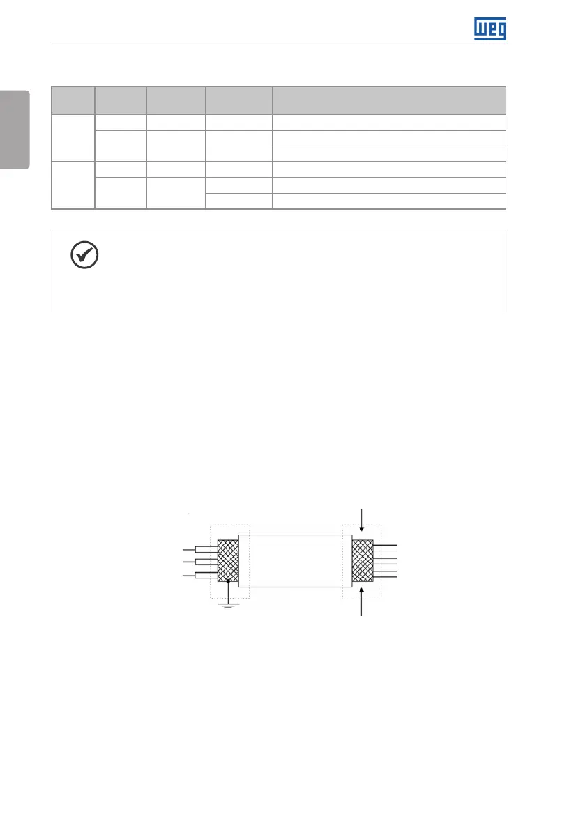
Connect the shield according to the figure below:
Do not ground
Insulate with tape
Inverter
side
Figure 3.5: Connection of the shield
4. Relays, contactors, solenoids or coils of electromechanical brake installed close to the
inverters may occasionally generate interference in the control circuitry. To eliminate this
effect, RC suppressors (with AC power supply) or freewheel diodes (with DC power supply)
must be connected in parallel to the coils of these devices.
5. When using the external HMI (refer to Section 7.2 ACCESSORIES on page 41), the cable
that connects to the inverter must be separated from the other cables in the installation,
keeping a minimum distance of 10 cm.