CFW500 | 25
Installation and Connection
English
6. When using analog reference (AI1) and the frequency oscillates (problem of electromagnetic
interference), interconnect the GND of the connector of the plug-in module to the inverter
grounding connection.
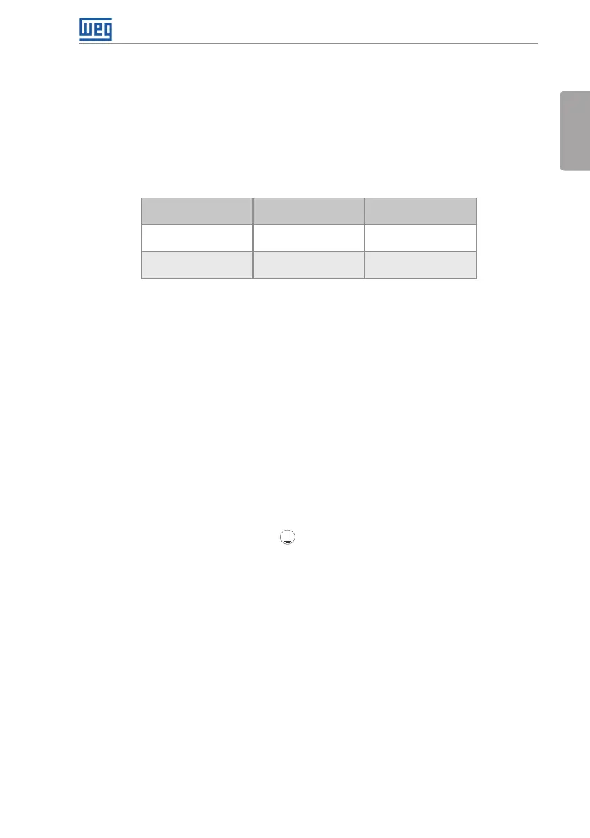
3.2.6 Cable Separation Distance
Provide separation between the control and power cables and between the control cables (relay
output cables and other control cables) as per Table 3.3 on page 25.
Table 3.3: Cable separation distance
Inverter Output
Rated Current
Length
of the Cable(s)
Minimum Separation
Distance
≤ 24 A
≤ 100 m (330 ft)
> 100 m (330 ft)
≥ 10 cm (3.94 in)
≥ 25 cm (9.84 in)
≥ 28 A
≤ 30 m (100 ft)
> 30 m (100 ft)
≥ 10 cm (3.94 in)
≥ 25 cm (9.84 in)
3.3 INSTALLATIONS ACCORDING TO EUROPEAN DIRECTIVE OF
ELECTROMAGNETIC COMPATIBILITY
Inverters with the option C2 or C3 (CFW500...C...) feature internal RFI filter to reduce the
electromagnetic interference. Those inverters, when properly installed, meet the requirements
of the directive of the electromagnetic compatibility (2014/30/EU).
For products without an internal filter, it is necessary to use an external filter in order to comply
with the EMC Directive.
The CFW500 inverter series was developed for professional applications only. Therefore, the
emission limits of harmonic currents by the standards IEC/EN 61000-3-2 and EN 61000-3-
2/A 14 are not applicable.
3.3.1 Conformal Installation
1. Inverters with option internal RFI filter CFW500...C... (with grounding switch of the capacitors
of the internal RFI filter in the position ) for frame sizes A to E or removing the grounding
screws of the internal RFI filter for frame size F. Check the location of the grounding switch in
Figure A.2 on page 153 or the position grounding screws of the internal RFI filter in Figure
A.4 on page 156).
2. Shielded output cables (motor cables) with shield connected at both ends, motor and inverter,
by means of a low impedance to high frequency connection.
Maximum motor cable length and conduced and radiated emission levels according to Table
B.6 on page 165. For more information (RFI filter commercial reference, motor cable length
and emission levels) refer to the Table B.6 on page 165.
3. Use shielded cables for the control connections, and keep them separate from the other
cables, according to Table 3.3 on page 25.
4. Grounding of the inverter according to instruction of the Item 3.2.4 Grounding Connections
on page 22.
5. Grounded power supply.