CFW500 | 19
Installation and Connection
English
Frame size F:
No minimum line impedance is required to prevent damages to the inverter and to guarantee
the expected service life.
3.2.3.3 IT Networks
ATTENTION!
When inverters with internal RFI filter are used in IT networks (neuter not
grounded or grounded through a high ohmic value resistor), always set the
grounding switch of the capacitors of the internal RFI filter to the NC position
(as shown in Figure A.2 on page 153) for frame sizes A to E or removing the
grounding screws of the internal RFI filter (indicated in Figure A.4 on page
156) for frame size F, since those kinds of network cause damage to the filter
capacitors of the inverter.
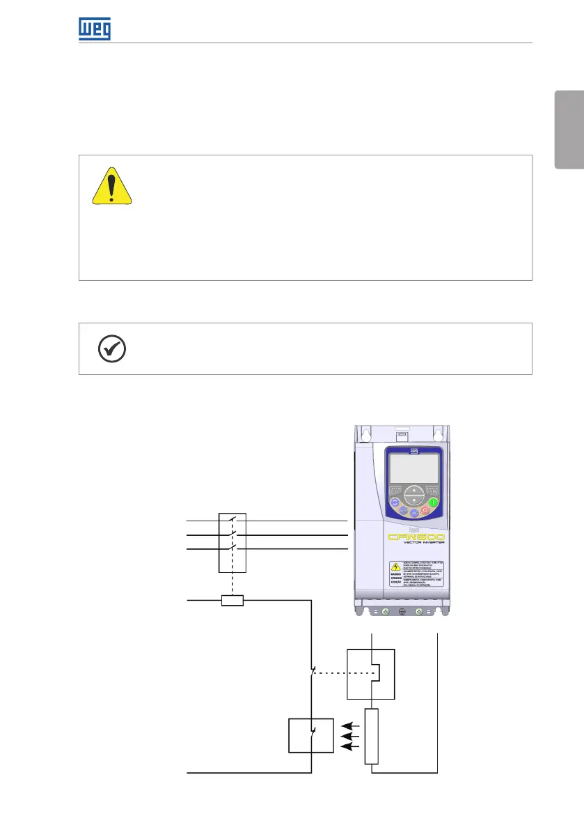
3.2.3.4 Dynamic Braking
NOTE!
The dynamic braking is available from frame size B.
Refer to Table B.1 on page 157 and Table B.2 on page 159 for the following specifications
of the dynamic braking: maximum current, resistance, effective current
(*)
and cable gauge.
Input power
supply
Thermostat
Brake
resistor
Relay
Command
power supply
Contactor
BR
+Ud
R
S
T
Figure 3.2: Installation of brake resistor