SSW7000 | 5-10
Installation and Connection
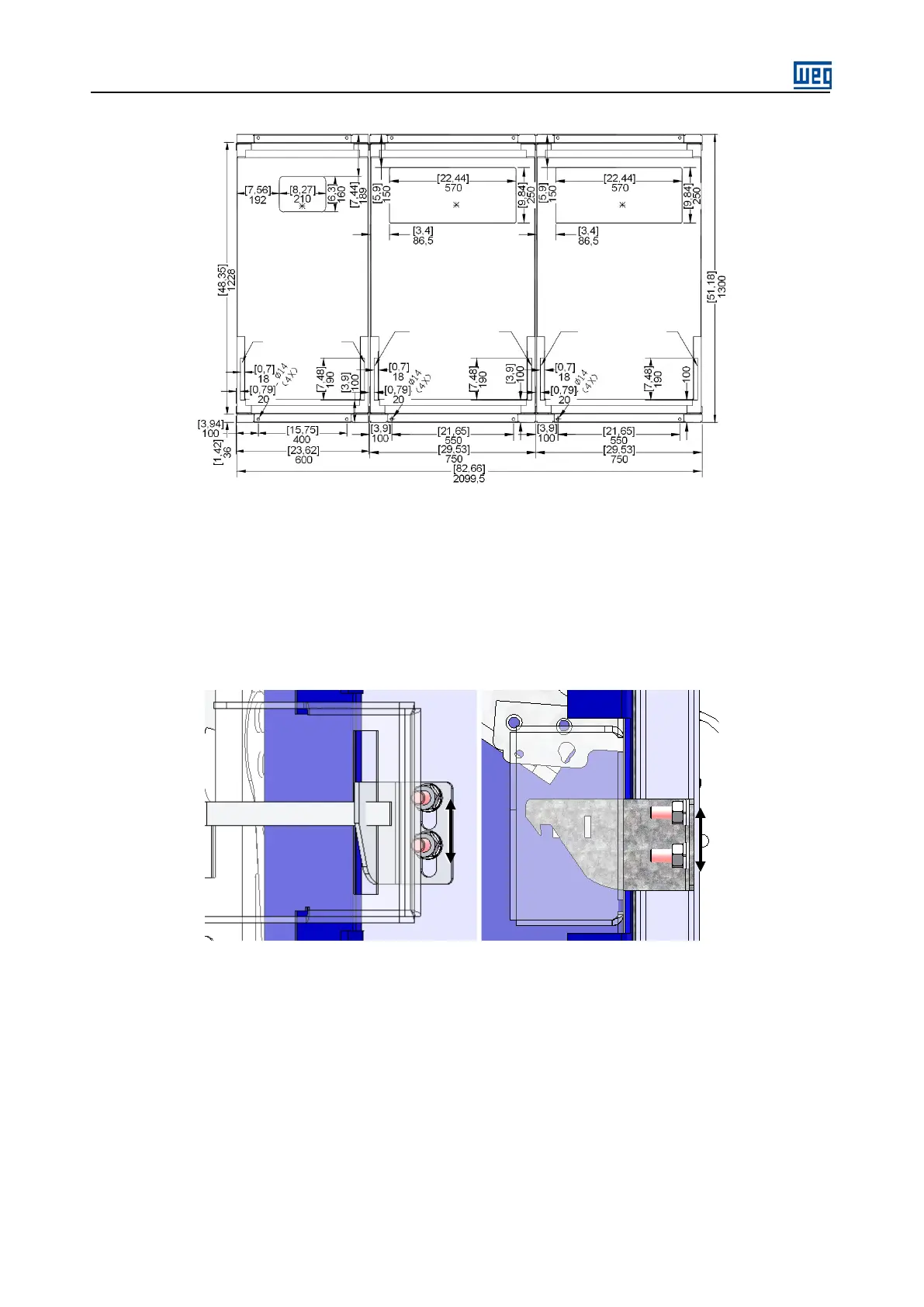
(c): IP41 Panel - SSW7000D
Figure 5.5 (c): Anchoring of the SSW7000D panel to the floor – dimensions in mm [in]
The adjustment of the mechanical interlock of the doors of the medium voltage compartment of the SSW7000
and SSW7000C is carried out at the factory. If any problem is detected in the mechanical interlock operation,
which may be caused by irregular surface where the panel is installed, for instance, adjust the locking part by
means of the bolts indicated in figure 5.6 and figure 5.7.
.
Figure 5.6: Position of the door interlock adjustment bolts of the medium voltage compartment – SSW7000.
L.V. cables
L.V. cables
L.V. cables