SSW7000 | 5-19
Installation and Connection
Table 5.16: Number of firing fiber optic cables per power arm
Table 5.17: Fiber optic cable identification
Fiber Optic Cable Identification
Terminal Color at the
Power Arm
R-U arm
Fire R – SCR firing cables
Temp. R – NTC themistorr cable
S-V arm
Fire S – SCR firing cables
Temp. S – NTC thermistor cable
T-W arm
Fire T – SCR firing cables
Temp. T – NTC thermistor cable
Precautions with the fiber optic cables:
1. Handle them with caution, in order not to fold, bend, squeeze or cut them.
2. To
insert or disconnect the cables, apply pressure or pull only at the connector, and never at
the cable.
3. Never bend the cables with a radius smaller than 40 mm (1.57 in).
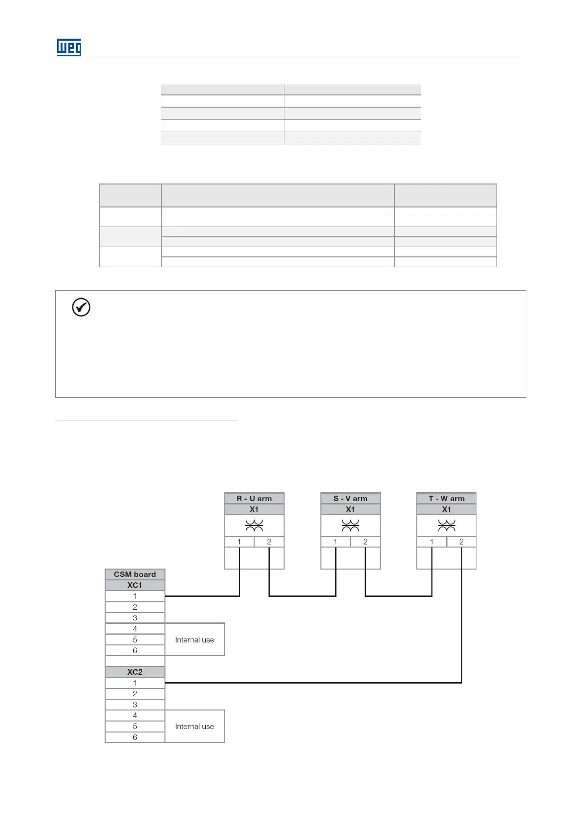
Firing boards power supply connections:
The connections of the firing boards power supply depends on the power arm rated voltage. In order to achieve
the proper supply operation, in version 2 (V2), always connect the three transformer sets in series, in version 3
(V3), always connect the transformers in parallel.
Figure 5.22: Insulated supply connections between the CSM2 board and the power arms of the model 2300 V (V2).
 Loading...


