Product description
Wieland Electric GmbH | BA000966 | 07/2016 (Rev. C)
24 V supply voltage of outputs Q1 - Q4
24 V supply voltage of configurable outputs IQ1 - IQ4
USB interface
The main module has a mini-USB interface with the following functions:
• Transfer of the configuration from samosPLAN5+ to the program removable storage
• Reading of configuration from program removable storage in samosPLAN5+
• Diagnostics of the samosPRO systems with samosPLAN5+
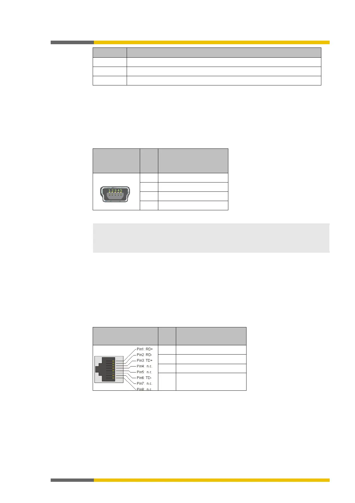
Table 9: USB interface pin assignment
• If the USB interface of the main module is permanently connected, then the maximum
permissible cable length is 3 m.
• Avoid using ground loops between the USB interface GND and the A2 connection of the
main module, e.g. by using optocouplers.
Ethernet interface
The main module has an Ethernet interface with the following functions:
• Transfer of the configuration from samosPLAN5+ to the program removable storage
• Reading of configuration from program removable storage in samosPLAN5+
• Diagnostics of the samosPRO systems with samosPLAN5+
• Continuous diagnostics of the samosPRO system via a connected PLC.
Table 10: RJ 45 bushing pin assignment
6 TD- / RD-
The device itself detects which cable type, patch cable or cross-link cable, is being used (Auto
MDI-X), which is why the pin assignment does not matter with regard to the RD or TD signals.