Connecting devices
Wieland Electric GmbH | BA000966 | 07/2016 (Rev. C)
Contactless safety sensors
888470539
Magnetic safety switches (e.g. SMA series)
888472075
888473611
Magnetic safety switches with equivalent inputs
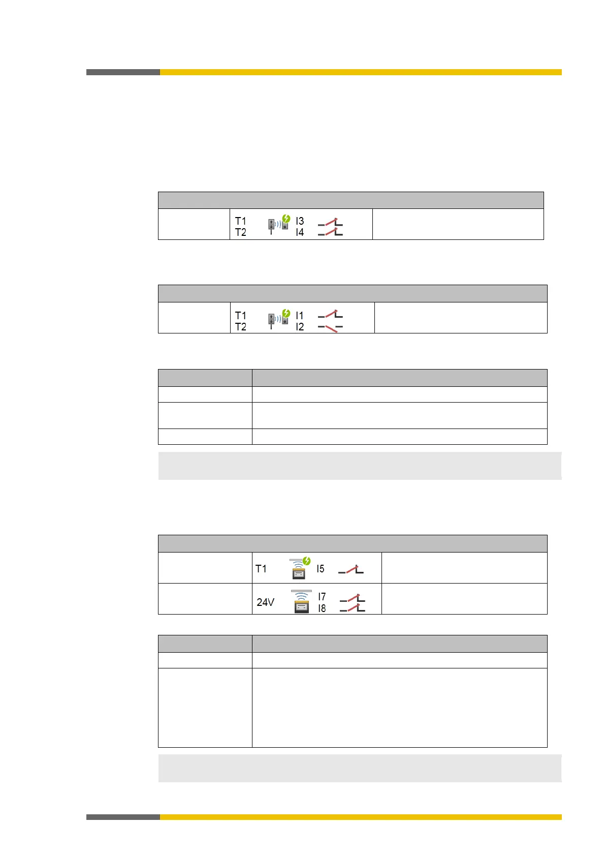
Table 26: Connection of magnetic safety switches with equivalent inputs
Electrical connection: Example from samosPLAN5+
With testing
Channel 1: Contact between T1 and I3
Channel 2: Contact between T2 and I4
888476299
Magnetic safety switches with complementary inputs
Table 27: Connection of magnetic safety switches with antivalent inputs
Electrical connection: Example from samosPLAN5+
With testing
NO contact between T1 and I1
NC contact between T2 and I2
Table 28: Functions with magnetic safety switches
Series connec-
Possible; note max. line resistance of 100 µ and correct setting of
You can find additional information in the operating instructions for the magnetic safety swit-
ches.
Inductive safety switches
888478987
Table 29: Inductive safety switch connection
Electrical connection: Example from samosPLAN5+
Inductive switch
(serial)
Test input TE at T1
Inductive switch
OSSD1 at I3
Table 30: Functions with inductive safety switches
Testing Necessary with serial inductive switches
Series connec-
tion/cascading
Inductive switches (serial):
Up to six sensors per input. Maximum OFF-ON delay of the cascade
is 10 ms (otherwise, the test gap will lead to switch-off). Note the
maximum line resistance of 100 Ω
and the correct setting of the test
pulse time.
Inductive switch: No cascading possible
You can find additional information in the operating instructions for the inductive safety swit-
ches.